
TOPIC FOCUS
Review every mechanical transition
The drawing set should identify stackups by region, bend intent, connector or stiffener geometry, keep-outs, coverlay openings, and assembly constraints.
Rigid-flex planning should distinguish rigid areas, flex areas, transition zones, bend use, coverlay, stiffeners, assembly handling, and the inspection conditions for the released construction.
The drawing set should identify stackups by region, bend intent, connector or stiffener geometry, keep-outs, coverlay openings, and assembly constraints.
A bend radius guideline is not a universal release rule. Material set, copper layout, layer count, bend cycles, thickness, and assembly exposure change the applicable limits.
Use this topic-specific checklist with the linked engineering reference. Record the actual project conditions and the agreed acceptance scope.
| Decision | Input to confirm | Record to retain |
|---|---|---|
| Bend use | Static or dynamic bend, direction and cycles | Mechanical requirement on drawing |
| Transitions | Region stackups, stiffeners and coverlay | Transition detail and keep-outs |
| Assembly | Fixture, connector and handling limits | Assembly support and inspection plan |
These records provide context for the topic. They do not replace review of the current files, materials, quantities, tests, or acceptance conditions.
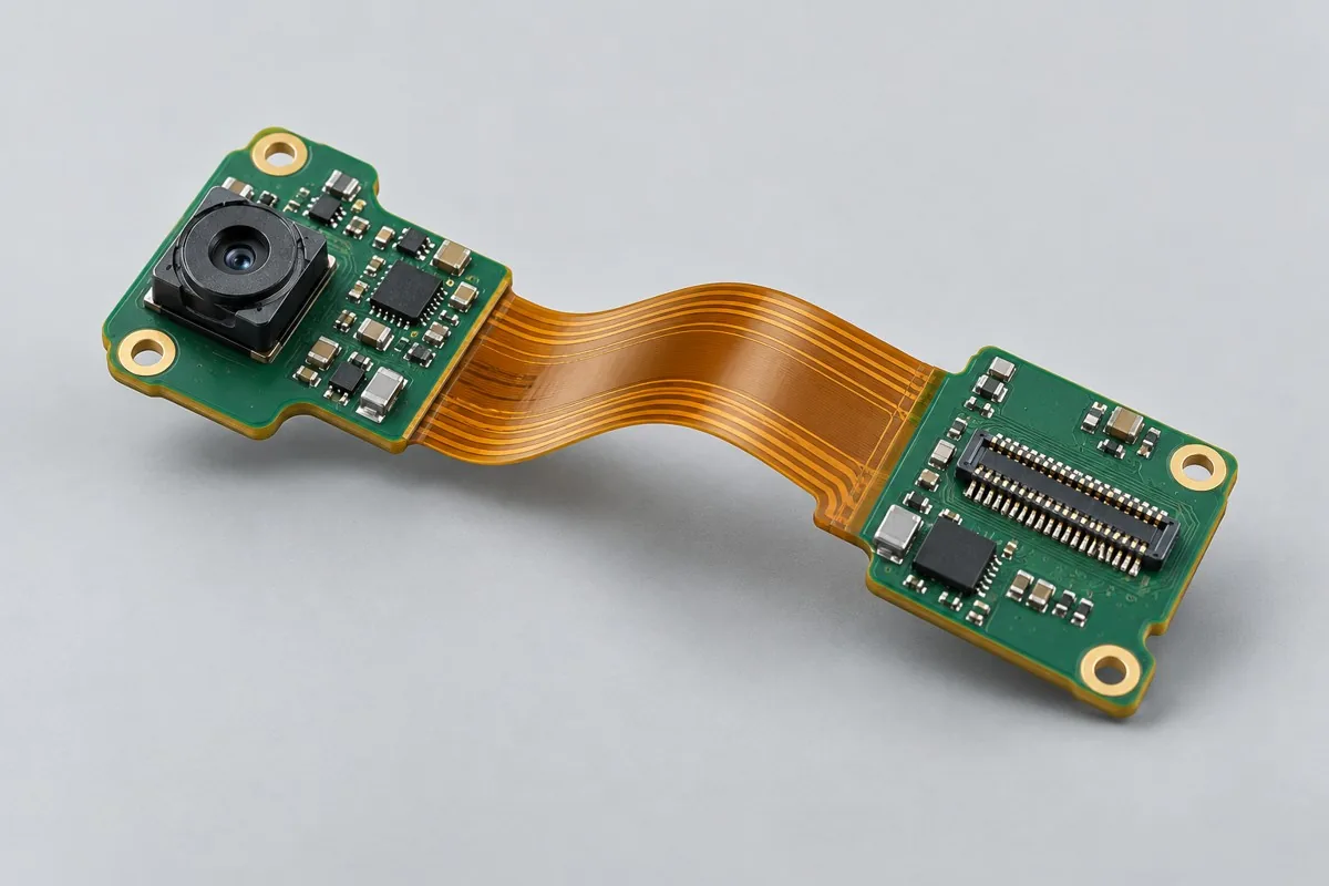
Camera interconnect board PCB assembly reference configurations cover fixed-bend connections between camera and processing ends. Separate carrier-supported rigid-region SMT, interface checks, formed assembly, and image testing; compare material supply, setup, and per-lot assembly costs. Check continuity, images, post-static-bend functionality, and assembly test scope, plus interconnect assembly + bend/assembly drawings + image-test deliverables.
A connection-board assembly reference for discussing flex handling and interconnect access.View Configuration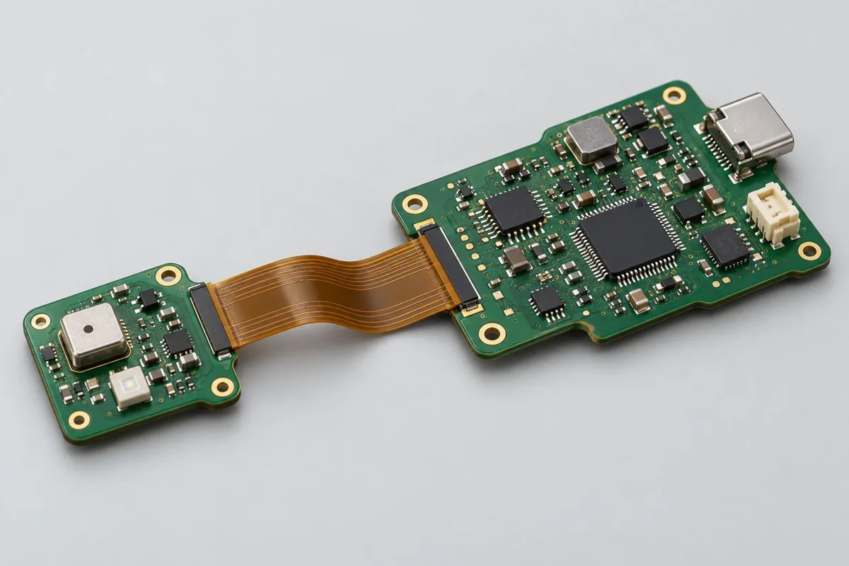
Sensor rigid-flex board reference configurations distinguish rigid placement regions, flexible connections, and installation forming. Compare carrier, placement, sensor calibration, and post-enclosure retest costs; check bending conditions, interfaces, and supporting structures, defining delivery records at each stage.
A rigid-flex assembly reference for coordinating mechanical transitions with assembly operations.View Configuration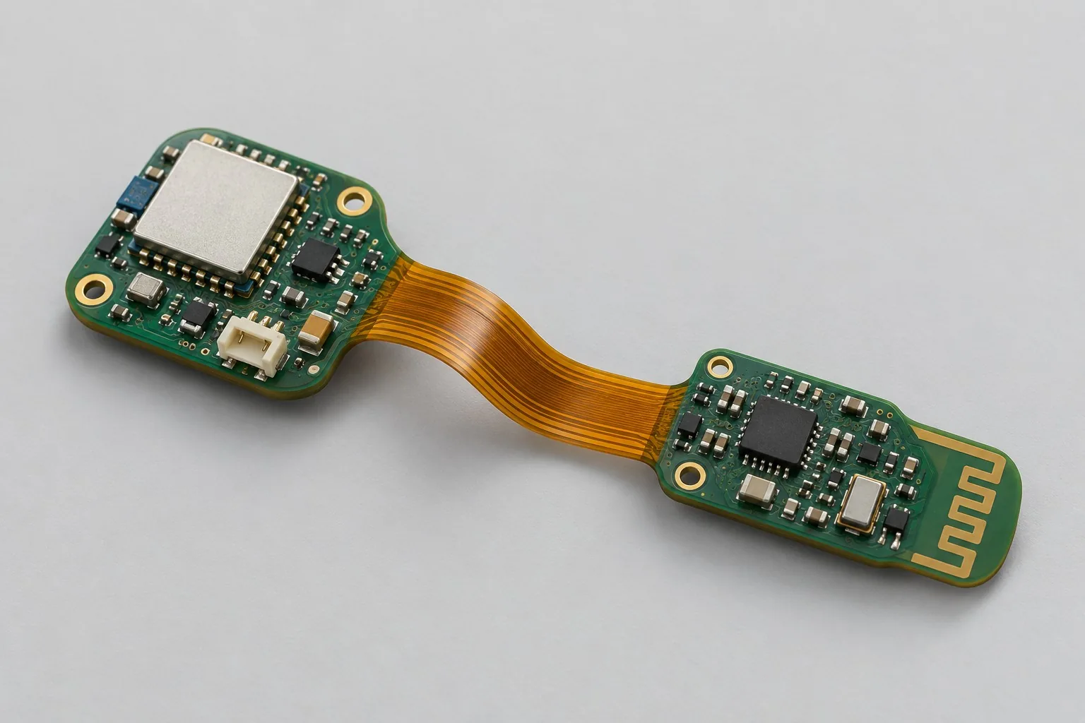
Wearable rigid-flex design: bundle basic motion acquisition, Bluetooth, and single-cell lithium power; separately list optional GNSS, charging structures, and system battery-life tests. Rigid 4-layer/flexible 2-layer construction awaits joint review. Confirm static forming/worn-position verification first; do not ambiguously bundle dynamic lifetime, positioning, and system tests into one rigid-flex fee.
A wearable rigid-flex design reference where bend intent and form factor need early review.View Configuration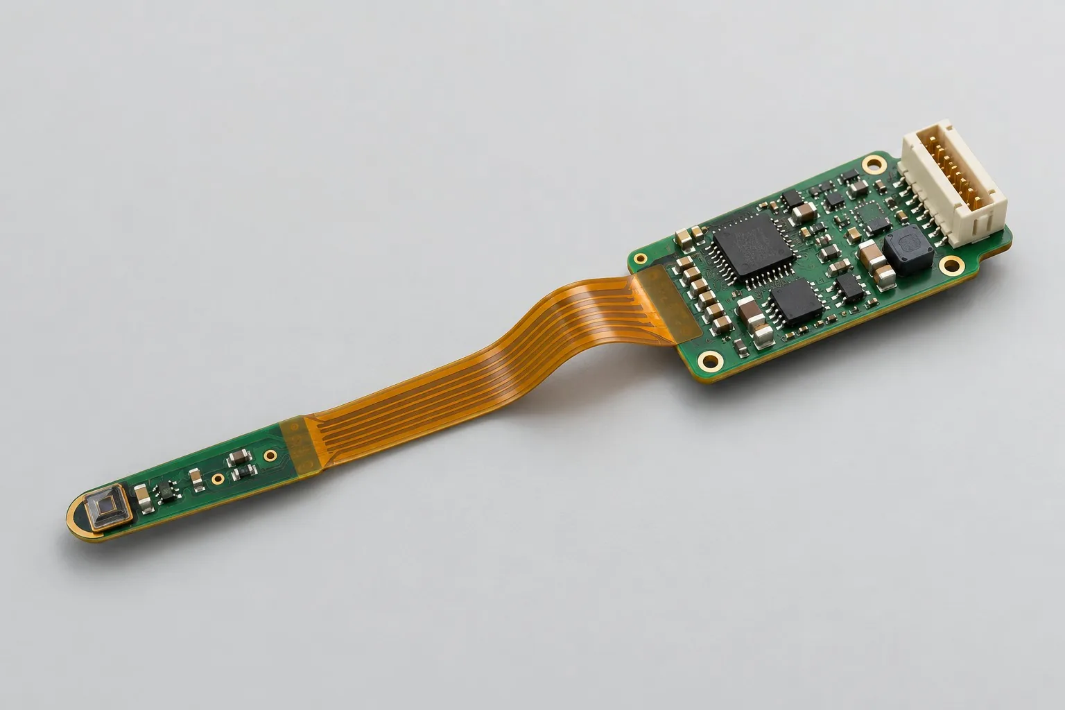
Rigid-flex sensor probe design: at identical probe locations and mainboard heat sources, list stackup/static folding for rigid-flex and connectors/buffering/maintenance for cables. Keep response and thermal-coupling verification identical before comparing materials and assembly. Eliminating one connector alone does not identify the cheaper design.
A sensor-probe design reference for relating flex geometry, connection, and production constraints.View ConfigurationUse this reference to check the essential inputs, then continue to the articles for specific methods and exceptions.

Distinguish static forming from dynamic bending first. A strain example explains thickness/radius relationships, with transition, coverlay, stiffener, and assembly-route checks. Staged continuity and physical evidence help locate bend-induced opens.
Read Topic ReferenceFive articles are shown per page, newest first. Page 1 of 1.
Compare related decisions. Browse all engineering topics
Share the available fabrication files, BOM, drawings, quantities, target schedule, test scope, and acceptance requirements. The response will be based on the actual project conditions.

Tell us the product use and which files are available. We can define the next engineering step even when the data package is not complete.