RF PCB fabrication: ports, shielding, and power division
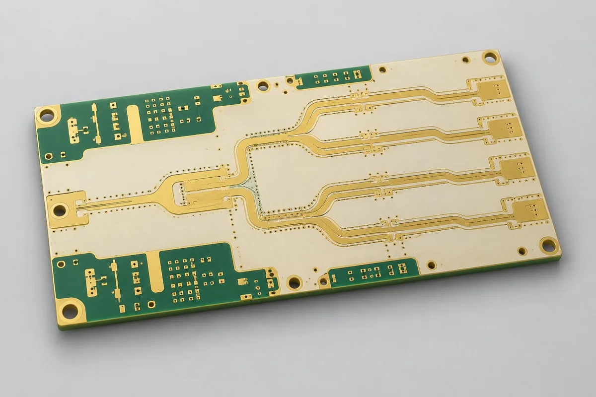
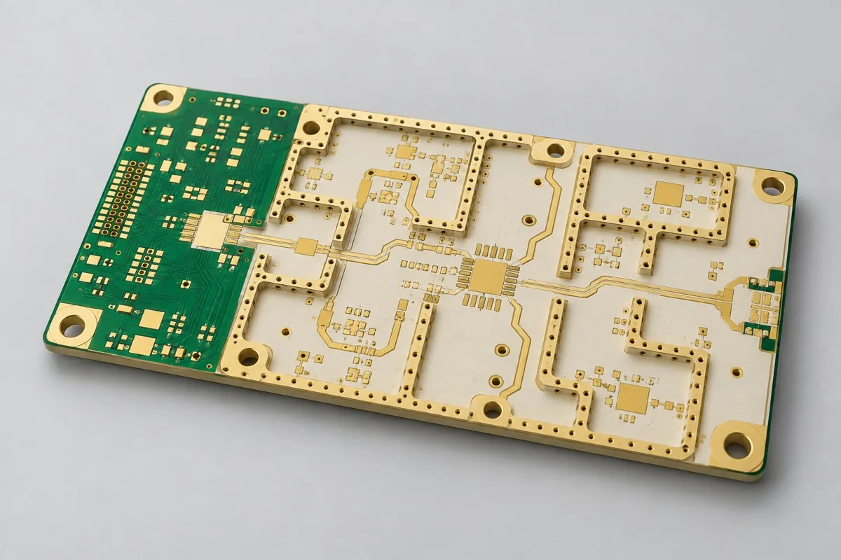
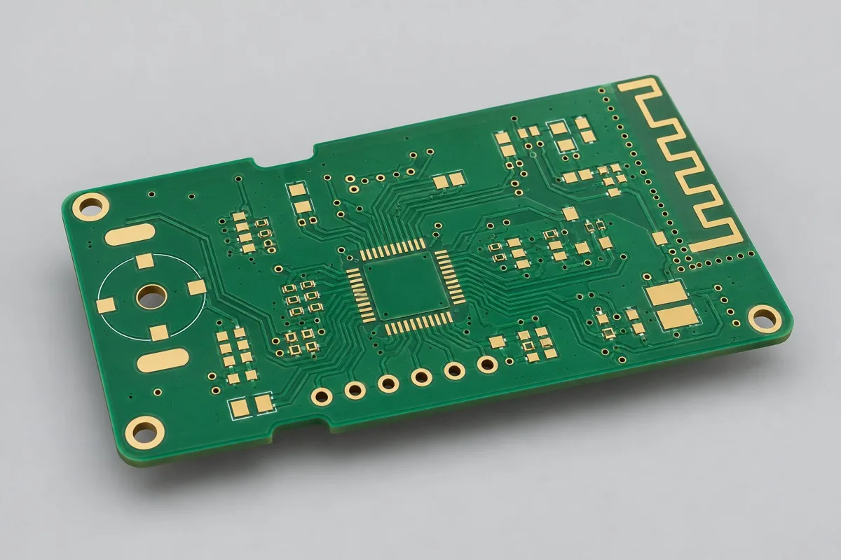
For RF bare PCB procurement, provide ports, matching areas, shield frames, or multi-channel amplitude/phase targets according to function. Sub-GHz short traces, specialty-dielectric front ends, and power-divider boards have different fabrication drawings and inspection objects; confirm ground vias and reference planes in quotations. Bare-board TDR cannot establish complete RF-system results.
RF interface inspection is part of acceptance
Specify connectors, matching areas, shield grounding, and test reference planes. Define functional targets separately for FR4 low-frequency wireless boards, specialty-dielectric RF front ends, and multi-channel power dividers; bare-board TDR cannot cover all RF results.
RF manufacturing: ports, shielding, and amplitude/phase
After selecting a product in this category, submit ports, matching areas, shield frames, ground-via fences, and multi-channel amplitude/phase targets. Match each change to the Engineering Reference Configuration, using the same revision for fabrication drawings, inspection locations, and material approvals; define specialized verification and report scope before quotation.
Adjacent direction:High-frequency material and band products · Functionally layered mixed lamination product · Custom Rogers structure products · RF functional products
Material and Process Reference
Consult selected PCB configuration
How should materials be selected for Sub-GHz RF boards and high-frequency front-end boards?
Sub-GHz short paths, RO4350B front ends, and power-divider boards have different loss and amplitude/phase requirements. FR4 suitability requires verification against length, frequency band, and targets; wireless functionality alone does not justify expensive materials.
How should ports and structures be determined for antenna, transmission-line, and power-divider PCBs?
Distinguish antenna, transmission, filtering, and power-division uses before determining materials and feedline structures. Bare-board continuity and impedance results cannot directly replace port or radiation verification of RF assemblies.
RF PCB pricing and selection FAQ
How much does RF PCB fabrication cost? Can ordinary wireless boards use FR4
A project-specific quotation requires review of the available files, quantity, materials, requested tests, delivery destination, taxes, shipping, and trade terms. Add specified materials, processes, and inspections not yet included to the total cost. Standard board references do not cover every configuration of this product. Any formula on this page organizes cost inputs; it is not a quoted rate.View cost items, calculation conditions, and sources.
How should I compare quotations from RF PCB manufacturers?
Align RF use, materials, ports, and trace lengths before comparing specified inspections. Bare-board continuity, assembly S-parameters, and antenna verification are different tasks; the latter two are not included in PCB fabrication fees by default.
Is FR4 always unsuitable for wireless boards?
Assess frequency band, path length, loss, and port budgets; FR4 can be considered for short paths. The RF label does not automatically require expensive materials; verify suitability for the actual task.
Do antenna, filter, and power-divider PCB quotes require the same inputs?
Provide installation/feed details for antennas, passbands and coupling for filters, and ports and amplitude/phase targets for power dividers. Distinguish uses before selecting materials and geometry; equal area does not establish equal performance.
Does an RF bare-board quote include network-analyzer measurements?
Define the boundary between manufacturing inspections and measurements of assemblies with connectors, listing reference planes and supporting items. Bare-board electrical tests or coupons do not automatically include actual-port S-parameters.
How should repeat orders be managed after matching adjustments change the BOM?
Turn tuned values into an approved production BOM linked to geometry and installation conditions. Do not directly reuse old matching tables for new antennas or materials; run regression tests across the target frequency band after changes.
Consult RF PCB quotation: describe the application, existing configuration, and expected quantity so we can discuss bare-board fabrication requirements, inspection, and delivery conditions.
How much does RF PCB fabrication cost? Can ordinary wireless boards use FR4
Quotes should separately account for materials and geometry required by the frequency band, RF connections, ground vias and surface finish, port reference planes, specified structures, and test support. List initial-order setup charges separately from per-batch and per-board charges; for equal quantities, also align revisions, delivery configurations, and tax and freight terms to identify whether price differences reflect configurations or excluded work.
Quotation terms depend on the approved files, quantity, material supply, tests and delivery requirements.
Prepare a structured RFQ or use the short inquiry form.