
Prototype Phase
Trial-fit with enclosure, antenna, harnesses, and actual loads, and check network configuration, sensor readings, and relay/motor operation.
For environmental sensing, appliance control, networking modules, and human-machine interaction, jointly check antennas, power, relay/motor drives, and complete-unit assembly.
Request Smart Home Assembly →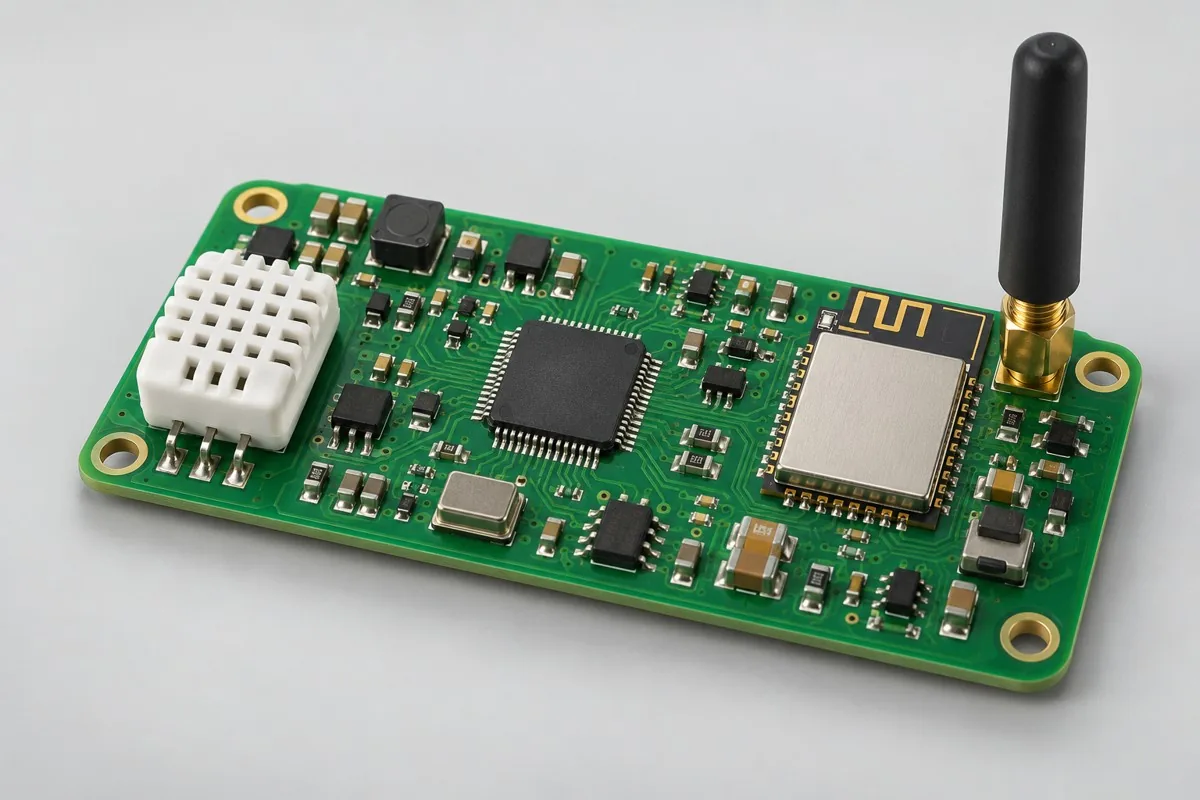
| Project Direction | PCB Manufacturing and Layout Focus | PCBA assembly and testing highlights |
|---|---|---|
| Wireless environment sensing board | RF-module antenna clearance, low-power supplies, and sensor exposure windows | Networking, sleep/wakeup, battery voltage, and sensor readings |
| Relay and motor control board | High-/low-voltage partitioning, slots and spacing, terminal current, and relay orientation | Output operation, load protection, indication states, and harness fastening |
| Smart Feeding and Water Pump Control Board | Moisture isolation, connector orientation, motor drives, and liquid-level interfaces | Timed operation, liquid-level/material-shortage feedback, fault shutdown, and firmware programming |
| Review Items | What specific inputs are provided | How to confirm results |
|---|---|---|
| System Structure | Enclosure, antenna, buttons, light guides, harnesses, and water-path samples | Trial-fit before freezing connector heights and screw-fastening methods |
| Safety and load | Power-supply method, insulation boundaries, actual loads, and protection conditions | Define test conditions by product application; low-voltage board tests cannot replace complete-unit safety validation |
| Networking and configuration | Programming-file checksums, network-configuration methods, unique IDs, and responsibility for account credentials and keys | Agree on programming, readback verification, data permissions, and finished-device unbinding methods |
Trial-fit with enclosure, antenna, harnesses, and actual loads, and check network configuration, sensor readings, and relay/motor operation.
Freeze configuration programming, unique IDs, fixture loads, and fault-shutdown tests; confirm effects of moisture protection, mechanical changes, and material changes.
Complete networking or configuration, sensing, and load cases using a consistent procedure; retain device-identity, unbinding, and exceptional-rework records as agreed for delivery.
For smart-home projects, in addition to Gerber, drill files, BOM, pick-and-place files/CPL, and assembly drawings, include operating environment, actual interfaces/loads, enclosure and harness drawings, target quantity, and the test limits above. If commissioning programming or calibration, add software revision, checksum, fixture wiring, and programming permissions.
Complete-unit safety, water-path, and protection validation require actual structures and loads; the agreed responsible party manages configuration tools, accounts, and keys.
View specific fabrication products by board-level task, or arrange a joint PCB fabrication and assembly review with complete information.
Engineering reference | QFN and SON assembly: thermal pads, printing, and solder joint verification: QFN/SON pad, stencil, and measured thermal process methods; not company capabilities.
Engineering reference | Packaging PCB fabrication files: units, layer order, and engineering notes: methods for PCB fabrication, hole layer spans, and file semantics.
| Work area | Inputs or responsibility | Expected output |
|---|---|---|
| Loads | Actuator type, supply and operating conditions | Define protection and abnormal-state checks |
| Sensing | Inputs, calibration and physical interfaces | Agree the conditions represented by each test |
| Harnesses | Connector, pin assignment, polarity and mechanical fit | Define assembly and continuity checks |
| System behavior | User commands, recovery and safe-state requirements | Identify board-level versus complete-system acceptance |
Use the acceptance and test responsibilities to prepare the discussion. Unknown inputs should be listed as open questions; they do not authorize substitutions, omitted tests or unrecorded design changes.

Tell us the product use and which files are available. We can define the next engineering step even when the data package is not complete.