
DDR storage interface motherboard design solution
First establish the controller, memory generation, and bus width, then select point-to-point or an applicable multidevice topology.
Accept DDR designs against controller topology and training requirements; accept dual-channel vibration designs against amplitude/phase, continuous buffering, and USB upload requirements. Check models, return paths, and power for both. Translate DDR timing or broadband acquisition data-path constraints into layout early, rather than defining whole-board performance solely by component rated speed.
Configurations in this category support development requirements discussions. Actual components, structures, and performance are confirmed in the project revision; historical development directions and engineering references are identified separately.
This category covers DDR memory and broadband vibration acquisition. Costs are broken down by schematic, PCB layout, agreed software, and prototype validation scope; the main workload differences involve model preparation, SI/PI budgets, constrained routing, and training/throughput testing. Layer count, board area, or channel count alone cannot determine development pricing; the usability of existing files and test conditions also affect the effort.
Quotation terms depend on the approved files, quantity, material supply, tests and delivery requirements.
Prepare a structured RFQ or use the short inquiry form.
| Quotation Items | What services are included | What to Check When Comparing Quotes |
|---|---|---|
| Existing circuit layout | Implement layout using approved schematics, footprints, and mechanical design | Whether schematic review, stackup/constraints, and fabrication files are included |
| From functional R&D | Model preparation, SI/PI budgets, constrained routing, and training/throughput testing | Whether circuits, firmware, and validation targets are complete |
| Prototypes and revisions | Build prototypes from the frozen design, record test feedback, and release a controlled revision | Whether prototype quantity, component procurement, and change scope use the same basis |
High-speed projects require specific topology, timing, and return-path constraints; trace count alone cannot determine pricing. DDR training and sustained acquisition throughput are different validation tasks and should be commissioned separately according to system objectives.
Start selection with the controller, speed, data width, and model availability, then review the parameters, cost boundaries, and validation conditions of the specific designs below.
| Review Questions | Why it impacts design | How to select and close |
|---|---|---|
| DDR and acquisition chain | DDR centers on controller topology, timing, and training; acquisition paths center on analog bandwidth, synchronization, and buffering. | Establish budgets around each bottleneck; one length-matching rule cannot replace constraints for all nets. |
| Models and simulation | Substrate parameters, packages, and interconnect models affect analysis conclusions. | Record model revisions and assumptions; where models are unavailable, identify conclusions that require prototype measurements for closure. |
| Power and return path | High-speed edges and load changes require continuous return paths and appropriate decoupling. | Review SI/PI, via layer transitions, and connectors together, rather than checking trace length alone. |
Controller and memory part numbers, speed grade, manufacturer topology, package/interconnect models, clock and training logs, and sustained-throughput target.
| Current Stage | Customer-Supplied Materials | Design deliverables |
|---|---|---|
| Functional requirements only | Controller and memory part numbers, speed grade, manufacturer topology, package/interconnect models, clock and training logs, and sustained-throughput target. | Functional/state requirements, approach comparison, mechanical design, and open items for DDR timing and broadband acquisition |
| Existing schematics or PCB | Editable circuit/PCB files, BOM, and mechanical design for products in this category; include controller and memory part numbers, speed grade, manufacturer topology, package/interconnect models, clock and training logs, and sustained-throughput target. | Net constraints, timing/SI/PI budgets, model list, and raw training or acquisition logs |
| Existing prototype pending revision | Fault reproduction conditions, raw logs/waveforms, test equipment, and original board revision | Troubleshoot faults related to DDR timing and broadband acquisition, and deliver revised files, an impact list, and regression records under the same operating conditions |
First establish the controller, memory generation, and bus width, then select point-to-point or an applicable multidevice topology.
For broadband filter settings, focus on frequency response; for low-latency settings, focus on control latency. Filter settings become part of the revision configuration.
Net constraints, timing/SI/PI budgets, model list, and raw training or acquisition logs. Link deliverables to the same requirements revision; the PCB fabricator confirms materials, stackup, holes, and fabrication conditions, while PCB assembly checks footprints, soldering, programming, and test points. Recheck this category's constraints after critical-component substitutions or mechanical changes.
Key validation in this category: DDR training and extended stress testing, sampling synchronization and bandwidth, sustained throughput, supply noise, and temperature rise.
| Acceptance Stage | Conditions to be frozen | Report Records |
|---|---|---|
| Functionality and boundaries | Component/software revisions, supply/load, and interface or mechanical operating conditions | Test procedures, raw logs/waveforms, results, and abnormal states |
| Application-specific performance | DDR training and extended stress testing, sampling synchronization and bandwidth, sustained throughput, supply noise, and temperature rise | Instruments and calibration, environment, samples, criteria, and exclusions |
| Version Closure | Change list, permitted limitations, passed items, and open items | Fabrication and software packages, test reports, and issue-closure records |
High-speed projects require specific topology, timing, and return-path constraints; trace count alone cannot determine pricing.
First specify the controller, speed, data width, and model availability.
Layout-only work can be discussed when usable schematics and component information exist. Starting from DDR memory or broadband vibration acquisition requirements requires selection and circuit design first. Itemize software, prototypes, and testing separately; do not treat layout fees as a complete development budget.
Itemize controller support, topology/models, training, and reads/writes for DDR; amplitude/phase and filtering, synchronization, buffering, and continuous upload for vibration acquisition. Align work stages rather than performance figures; trace length or data rate cannot directly determine price comparisons. Define test equipment and raw-record delivery separately.
The responsible project party must first define DDR group topology/timing or the acquisition common-clock and data-path constraints. Length matching is only part of implementation; reference planes, vias, power, and model gaps still need review. Approved constraints can narrow the commission; without constraints, it cannot be quoted as conventional routing.
DDR software includes initialization, training, and memory stress testing; vibration software includes DMA, filter settings, sequence numbers, and disk recording. Customers can provide existing tools, but the new board still needs regression under the same conditions. IBIS simulations or length-matching screenshots do not replace startup and continuous-data validation.
Retain exact controller/ADC part numbers, model revisions, stackup, and grouped net constraints; list supplemental measurements where models are unavailable. Deliver software and raw training/dropped-sample logs with each revision. After component substitution, revalidate affected paths rather than only checking whether pads match.
For DDR, confirm controller and memory support, timing, and SI/PI; for acquisition, confirm analog bandwidth, filtering, buffering, and upload. List model, layout, software, and test changes separately; increasing rated speed may affect the entire path and cannot be treated as a free parameter change.
Reference-plane and power-review methods can be adapted, but DDR bus rules cannot be applied directly to analog amplitude/phase and common clocks. Evaluate retaining existing tools or debug interfaces; develop the ADC front end, synchronization, and continuous recording around acquisition tasks rather than conflating technical conclusions under the term high-speed.
Initially describe the product task, application, and current files. A formal quotation should confirm controller and memory part numbers, speed grade, manufacturer topology, package/interconnect models, clock and training logs, and sustained-throughput target. If source files exist, provide circuit/PCB/BOM and mechanical revisions together; if prototypes exist, include fault conditions. First identify frozen functions and structures, then compare circuit, layout, software, and validation work; unresolved items must not be assumed to share the same service scope.
Key validation in this category: DDR training and extended stress testing, sampling synchronization and bandwidth, sustained throughput, supply noise, and temperature rise. For each RFQ item, specify the actual load/interface or structure, prototype quantity, measurement method, equipment, and permitted deviation; deliver raw results, anomalies, and revision closure separately. Circuit/PCB checks and complete-unit functional validation are different tasks; a quotation including only the former does not justify omitting the performance measurements specific to this category.
Select and place components using the manufacturer information in the specific design details, and record file revisions and applicable conditions with the project; the company's historical development directions do not mean the reference designs on this page have been delivered in volume.
Return to the electronics design technical section · PCB Manufacturing · PCB assembly · Submit R&D requirements. When requesting high-speed PCB design, prepare functions, interfaces, board outline, and existing design information.
Send the product functions, interfaces, mechanical constraints, available files, and required development stage. Compare design capability scope and development support before defining deliverables.
Compare reference designs by function, interfaces, and mechanical constraints, including design tradeoffs and prototype-acceptance methods.
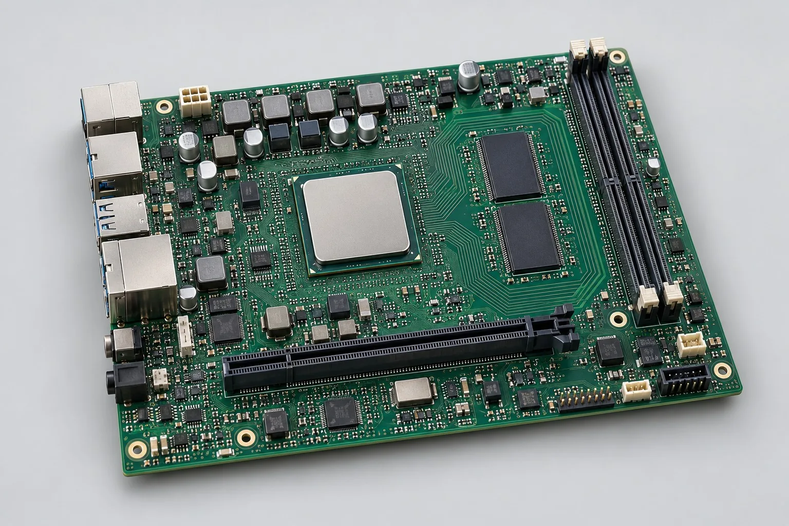
High-speed DDR PCB design: if controller model, DDR3L x16 example, packages, or initialization are undefined, review support and topology first. Commission eight-layer layout after usable constraints exist; separate modeling, training debug, and read/write stress tests to avoid discovering unsupported component/pin combinations after routing.
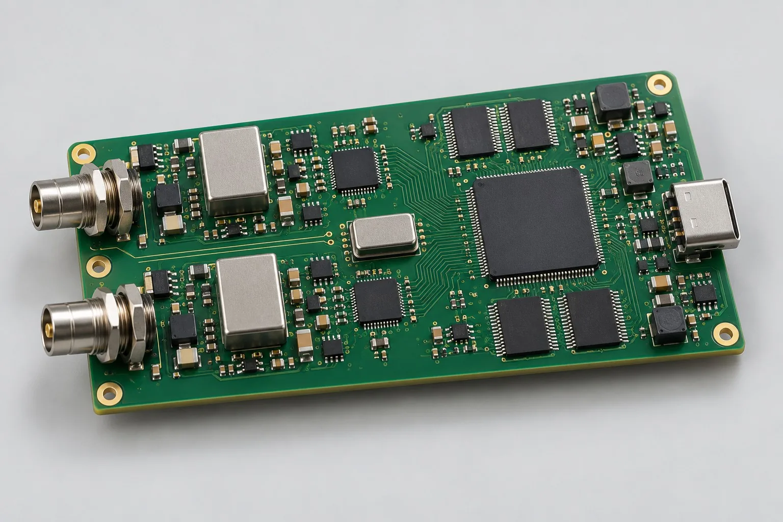
Vibration acquisition board design: review front ends using defined differential voltage inputs and target bands first, then validate ADCs, DMA buffers, and sustained USB data using a dual-channel 200kSPS example. List IEPE excitation, waveform software, and complete-sensor tests as separate options so basic voltage-acquisition and expanded sensor budgets can be compared independently.

Tell us the product use and which files are available. We can define the next engineering step even when the data package is not complete.