
Prototype Phase
Check IMU orientation, vibration-isolated mounting, harness fastening, and battery range. Verify interfaces and drives on a controlled bench first.
For flight controls, electronic speed controllers, communication, and sensor modules, focus on lightweight construction, vibration isolation, current paths, IMU orientation, and bench testing.
Consult drone board fabrication →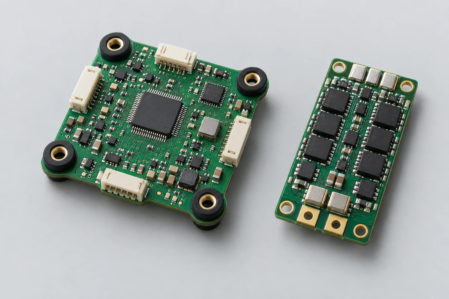
| Project Direction | PCB Manufacturing and Layout Focus | PCBA assembly and testing highlights |
|---|---|---|
| Flight Control Board | IMU orientation, mounting holes, connector heights, sensitive power supplies, and sensor placement | Sensor self-tests, orientation/calibration writing, communication, and inputs/outputs |
| Power regulation and power boards | MOSFET thermal paths, high-current copper foil, pads, and power inputs | Staged loaded testing, drive waveforms, protection, and temperature rise |
| Image transmission and positioning module | RF feedlines, shielding, harness strain, and antenna interfaces | Links, positioning, power disturbances, and interface stability |
| Review Items | What specific inputs are provided | How to confirm results |
|---|---|---|
| Mechanical and Vibration | Board outline, weight, hole positions, vibration dampers, harness fastening, and IMU orientation | Jointly confirm mechanical trial assembly and vibration conditions to prevent fastening from changing sensor behavior |
| Power and Supply | Battery range, peak current, switching frequency, and cooling conditions | Use current limiting and stepped loads on the bench, recording protection actions and thermal distribution |
| Function and Delivery | Firmware/configuration, sensor calibration, communication ports, and failure handling | Record and sign off board-level/powertrain bench/complete aircraft flight tests separately |
Check IMU orientation, vibration-isolated mounting, harness fastening, and battery range. Verify interfaces and drives on a controlled bench first.
Confirm sensor calibration, stepped loads, protection, and thermal processes. Freeze board-level inspection and powertrain bench steps separately.
Deliver boards linked to firmware configuration, sensor calibration, and load records. The agreed responsible party verifies complete aircraft flight tests and operating conditions.
For drone projects, provide Gerber files, drills, BOM, pick-and-place files, and assembly drawings, plus operating environment, actual interfaces/loads, enclosure and harness drawings, target quantity, and the test limits above. If programming or calibration is commissioned, add firmware revision, checksum, fixture wiring, and writing permissions.
Approve test conditions separately for powertrain benches, environmental tests, and complete aircraft flight tests. Board-level acceptance is not a flight performance conclusion.
View specific fabrication products by board-level task, or arrange a joint PCB fabrication and assembly review with complete information.
Engineering reference | QFN and SON assembly: thermal pads, printing, and solder joint verification: QFN/SON pad, stencil, and measured thermal process methods; not company capabilities.
Engineering reference | Packaging PCB fabrication files: units, layer order, and engineering notes: methods for PCB fabrication, hole layer spans, and file semantics.

Tell us the product use and which files are available. We can define the next engineering step even when the data package is not complete.