
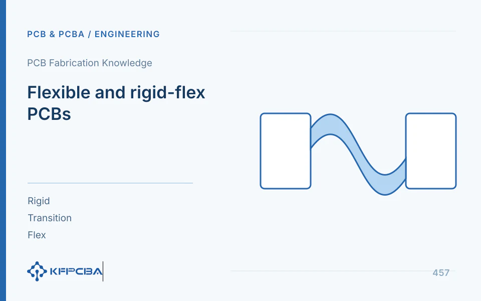
A bendable flex region does not make every structure suitable for repeated motion. Distinguish one/few static forming operations from long-term dynamic bending, then define direction, radius, cycles, frequency, temperature, and mounting. A minimum radius without these conditions cannot cover every task.
Write bends as actual assembly actions
Record the complete route from flat transport to installation, including bending stage, fastening responsibility, reverse bends, and twisting. Dynamic applications also need motion range, cycle frequency, and environment. The manufacturer's Flex Solutions guide emphasizes mechanical/electrical/manufacturing coordination; establish these inputs early.
One successful static installation establishes that assembly only, not dynamic life. Repeated service removal differs from continuous motion. Mark actual bend zones, fixed points, and free lengths so tests use matching constraints.
The structure list needs more than a PI film designation
| Structural Item | Verification Content | Potential Impact |
|---|---|---|
| Conductor | Copper foil, copper thickness, layer count, and trace distribution | Bending strain and fatigue sensitivity |
| Insulation and Coverage | Substrate, adhesive, cover film, and window opening | Total thickness, local stiffness, and protection |
| Rigid-Flex Transition | Layer termination, outline, via, and pad distance | Stress Concentration and Tearing |
| Reinforcement and Fixing | Materials, location, bonding, and assembly | Bend location and force transmission |
Thicker multilayer-copper structures have more complex neutral axes; PI thickness alone is insufficient. Check rigid/flex thickness, references, and impedance together so flexibility changes do not compromise electrical loops.
A strain example relating thickness to radius
For an ideal homogeneous thin strip in pure bending with a central neutral axis, outer strain is approximately ε=t/(2R). At t=0.10 mm and R=5 mm, strain is approximately 0.01, or 1%. At the same radius with 0.20 mm thickness, it is approximately 2%. Greater thickness can significantly increase bending strain.
Actual flex PCBs combine copper, resin, adhesive, and coverlay. Neutral axes may be off-center, and copper strain differs from the example's surface value. This is neither allowable strain nor recommended radius/lifetime; calculate or test actual materials/structures.
Reduce local concentration in transitions and routing
The manufacturer's guide recommends keeping holes and abrupt width/direction changes out of bends, and suitable separation between holes/SMD pads and rigid-flex transitions. Confirm dimensions for the actual structure/rules. Sharp corners, notches, and stiffener ends can concentrate bending; inspect each mechanically.
- Mark bend axes/motion directions and review conductor direction/distribution.
- Check holes, pads, coverlay openings, and stiffener boundaries near transitions.
- Prevent assembly from turning free bending into creasing, pinching, or tension.
- Review copper/references jointly for flexibility, signals, and current.
- Give pilot personnel assembly sequences/protection requirements and retain actual operation records.
Design intent must work physically. A drawn large arc becomes irrelevant if enclosure edges force a sharp fold; the actual fold is the test object.
How to locate open circuits after bending in stages
| phase | Inspection | Interpretation Direction |
|---|---|---|
| Flat Lay Before Assembly | Conduction, appearance, and structural identity | Establish original state |
| Unfixed after forming | Same network conduction and bending location | Identify bending action impact |
| Fixed and after enclosure assembly | Conductivity, clamping, and contact | Identify assembly constraints |
| After dynamic or environmental testing | Continuity, appearance, and abnormal locations | Identify cycles and environmental effects |
Restored continuity after loosening mounts still requires crack/contact investigation, not direct acceptance. For transition opens, preserve local structure/assembly marks; near joints, distinguish soldering from flex tension. Locate failures before sampling so cutting does not destroy clues.
What records are required for bend testing
Use actual structure, foil, coverlay, stiffeners, and fastening in specimens. Define radius measurement, angle, cycles, speed, direction, environment, and continuity monitoring, with criteria from product tasks/approval. Machine motion must represent field motion, beyond cycle counts.
Continuous monitoring during dynamic tests helps catch intermittent opens missed by final static tests. The test owner defines equipment, sampling, and criteria. Record individual samples, not average life alone, preserving failed locations/conditions.
How to approve structure and assembly after modification
Measures may change flex layer count, materials, routing, transitions, stiffeners, or mounting. Explain intended effects and electrical impacts, comparing consistent records. Changing everything may solve the problem but obscure necessary factors and future cost-reduction bases.
Approval outputs include planar/three-dimensional bend paths, layer structures, assembly steps, and results. Define transport carriers, solder supports, and post-inspection protection to prevent later overbending. Reconfirm impacts of critical repeat-order changes.
Reproduce actual bend paths between testing and assembly
Use consistent drawing/sample datums, marking fixed/free edges and bend start/end. Confirm available flex length with assembly tolerances so worst cases do not pull taut. Record natural transport bends, forming, and final motion separately instead of merging every action into one undefined radius.
Step photos/diagrams can show assembly order but must match approved samples. Fixtures should support required locations without new indentations near transitions/joints. If forced creasing is needed, pilot staff should report mechanical issues rather than hide special handling techniques.
Match dynamic-test clamping, angles, and speeds to actual motion. Cylinder cycling differs from products with twisting/sliding friction. Explain representativeness and list uncovered motions; equal cycle counts alone do not establish equivalence.
Inspect conductors and cover layers in open-circuit analysis. Crack positions, intermittent-open angles, recovery conditions, and force directions aid location. Preserve installed conditions before disassembly; distinguish new disassembly creases from original marks so they are not confused with causes.
After improvements, have assembly/testing each execute the same path and compare records. Resolve interpretation differences before scaling production. Approval then covers reproducible forming/fastening in the product, beyond a flat drawing.
Frequently Asked Questions
Does larger radius guarantee infinite reliability
Radius is only one factor; materials, structures, defects, twisting, and environment also matter.
Can static-bend data support dynamic products?
Not automatically; match the actual task. Continue to Manufacturing Combination and Manufacturing Data Checklist.
Source material and applicable scope
- Würth Elektronik, “Design Guide Flex Solutions”; Version 06.2025 / 504720 EN; checked on 2026-10-17; relevant sections: mechanical inputs, Dynamic Bending, Layout and Routing, and rigid-flex transitions. Supports static/dynamic distinctions and joint structure/assembly review. The strain example uses a homogeneous thin-strip model, not universal flex radii or lifetime.
