
Aluminum-core high-power LED module design
Aluminum-core PCB heat conduction is only one part of the thermal path; dielectric, interface contact, and heatsink must all enter the thermal budget.
Compare aluminum-core LED modules and separate low-voltage power boards; calculate the complete thermal path through dielectric, TIM, and heatsink, and check installation, insulation, and continuous-load conditions. Metal-core PCB design centers on the complete component-to-heatsink thermal path, distinguishing standalone LED modules from separate control/power structures.
Configurations in this category support development requirements discussions. Actual components, structures, and performance are confirmed in the project revision; historical development directions and engineering references are identified separately.
This category covers aluminum-core LED modules and separate IMS power stages. Costs are broken down by schematic, PCB layout, agreed software, and prototype validation scope; the main workload differences involve thermal paths, dielectric/installation fit, and load temperature-rise tests. Layer count, board area, or channel count alone cannot determine development pricing; the usability of existing files and test conditions also affect the effort.
Quotation terms depend on the approved files, quantity, material supply, tests and delivery requirements.
Prepare a structured RFQ or use the short inquiry form.
| Quotation Items | What services are included | What to Check When Comparing Quotes |
|---|---|---|
| Existing circuit layout | Implement layout using approved schematics, footprints, and mechanical design | Whether schematic review, stackup/constraints, and fabrication files are included |
| From functional R&D | Thermal paths, dielectric/installation fit, and load temperature-rise tests | Whether circuits, firmware, and validation targets are complete |
| Prototypes and revisions | Build prototypes from the frozen design, record test feedback, and release a controlled revision | Whether prototype quantity, component procurement, and change scope use the same basis |
Compare the complete heat-source-to-heatsink path, rather than material thermal conductivity alone. IMS structures also face dielectric-insulation and routing constraints; separate control and power boards add connection and testing work.
Start selection with heat generation, insulation requirements, mounting interfaces, and continuous loads, then review the parameters, cost boundaries, and validation conditions of the specific designs below.
| Review Questions | Why it impacts design | How to select and close |
|---|---|---|
| Thermal chain and dielectric | A metal base does not automatically make component temperatures acceptable; dielectrics and interfaces may be bottlenecks. | Calculate and measure the component-to-ambient thermal path, identifying thermal-resistance definitions and installation conditions. |
| Functional Segmentation | Complex control boards and high-current thermal boards have different routing requirements. | Compare separate control and IMS power boards, and freeze board-to-board interfaces and fault states. |
| Mechanical and insulation | Screws, board edges, and metal bases affect insulation and assembly. | Confirm insulation layers, mounting torque, interface materials, and inspectable assembly requirements. |
Component losses, insulation requirements, dielectric thermal parameters, board thickness, heatsink and interface materials, environment, and mechanical installation.
| Current Stage | Customer-Supplied Materials | Design deliverables |
|---|---|---|
| Functional requirements only | Component losses, insulation requirements, dielectric thermal parameters, board thickness, heatsink and interface materials, environment, and mechanical installation. | Functional/state requirements, approach comparison, mechanical design, and open items for LED modules and separate power stages |
| Existing schematics or PCB | Editable circuit/PCB files, BOM, and mechanical design for products in this category; include component losses, insulation requirements, dielectric thermal parameters, board thickness, heatsink and interface materials, environment, and mechanical installation. | Thermal budget, IMS structure and dielectric conditions, installation drawings, and temperature-rise and insulation records |
| Existing prototype pending revision | Fault reproduction conditions, raw logs/waveforms, test equipment, and original board revision | Troubleshoot faults related to LED modules and separate power stages, and deliver revised files, an impact list, and regression records under the same operating conditions |
Aluminum-core PCB heat conduction is only one part of the thermal path; dielectric, interface contact, and heatsink must all enter the thermal budget.
Moving heat sources to a separate board may improve control-board temperature, but board-to-board parasitic inductance affects switching and protection.
Thermal budget, IMS structure and dielectric conditions, installation drawings, and temperature-rise and insulation records. Link deliverables to the same requirements revision; the PCB fabricator confirms materials, stackup, holes, and fabrication conditions, while PCB assembly checks footprints, soldering, programming, and test points. Recheck this category's constraints after critical-component substitutions or mechanical changes.
Key validation in this category: temperature rise under agreed installation conditions, contact and insulation, and functional and mechanical condition after thermal cycling.
| Acceptance Stage | Conditions to be frozen | Report Records |
|---|---|---|
| Functionality and boundaries | Component/software revisions, supply/load, and interface or mechanical operating conditions | Test procedures, raw logs/waveforms, results, and abnormal states |
| Application-specific performance | Temperature rise under agreed installation conditions, contact and insulation, and functional and mechanical condition after thermal cycling | Instruments and calibration, environment, samples, criteria, and exclusions |
| Version Closure | Change list, permitted limitations, passed items, and open items | Fabrication and software packages, test reports, and issue-closure records |
A project-specific quotation requires review of the available files, quantity, materials, requested tests, delivery destination, taxes, shipping, and trade terms. Complete development separately prices circuits, firmware, prototypes, and verification. Any formula on this page organizes cost inputs; it is not a quoted rate.View cost items, calculation conditions, and sources.
Compare the complete heat-source-to-heatsink path, rather than material thermal conductivity alone.
First specify heat generation, insulation requirements, mounting interfaces, and continuous loads.
Layout-only work can be discussed when usable schematics and component information exist. Starting from aluminum-core LED module or separate IMS power-stage requirements requires selection and circuit design first. Itemize software, prototypes, and testing separately; do not treat layout fees as a complete development budget.
For LED boards, list optical arrangement and the thermal path with external constant-current drivers; for IMS power daughterboards, list switching, gate drive, Kelvin connections, and control-board connections. Material/installation reviews can form shared stages, while actual-load and fault tests are itemized separately. Metal-board area or thermal conductivity alone cannot determine development-cost comparisons.
Specify dielectric/copper weight, component losses, screw holes, interface materials, and heatsink; for power boards, also provide control loops and terminals. Layout only implements approved circuits and thermal structures. Perform thermal/mechanical review first if mounting conditions are missing; a metal substrate does not automatically eliminate temperature-rise risks.
A passive LED board may need no software, while PWM, fault readback, and protection recovery for power boards need an assigned responsible party. Specify which board holds the NTC and controller; even existing controller code needs integrated debugging with new power/thermal paths. A thermal-board label does not mean there is no control work.
Agree on dielectric, screw-hole/board-edge insulation, thermal interfaces, and installation dimensions, and deliver editable PCB files with corresponding fabrication requirements. Retain actual load, fastening, and cooling conditions in reports; include board-to-board connections for power boards, allowing recalculation of the complete thermal path when replacing heatsinks later.
Compare materials and dielectrics under the same heat-generation, mounting, and insulation conditions, and reconfirm weight, fabrication, and interfaces. Itemize design-source-file and thermal-measurement changes separately; higher metal thermal conductivity does not guarantee lower complete-unit temperatures, and bare PCB purchase price alone is insufficient.
First reassess the metal base, dielectric, and screw-hole boundaries against product operating/transient voltages, insulation, and mechanical fastening. Thermal mounting methods may be reusable, but insulation coordination and approved tests are separate tasks. A thermally conductive dielectric does not establish compliance with arbitrary high-voltage system safety requirements.
Initially describe the product task, application, and current files. A formal quotation should confirm component losses, insulation requirements, dielectric thermal parameters, board thickness, heatsink and interface materials, environment, and mechanical installation. If source files exist, provide circuit/PCB/BOM and mechanical revisions together; if prototypes exist, include fault conditions. First identify frozen functions and structures, then compare circuit, layout, software, and validation work; unresolved items must not be assumed to share the same service scope.
Key validation in this category: temperature rise under agreed installation conditions, contact and insulation, and functional and mechanical condition after thermal cycling. For each RFQ item, specify the actual load/interface or structure, prototype quantity, measurement method, equipment, and permitted deviation; deliver raw results, anomalies, and revision closure separately. Circuit/PCB checks and complete-unit functional validation are different tasks; a quotation including only the former does not justify omitting the performance measurements specific to this category.
Select and place components using the manufacturer information in the specific design details, and record file revisions and applicable conditions with the project; the company's historical development directions do not mean the reference designs on this page have been delivered in volume.
Return to the electronics design technical section · PCB Manufacturing · PCB assembly · Submit R&D requirements. When requesting metal-core PCB design, prepare functions, interfaces, board outline, and existing design information.
Send the product functions, interfaces, mechanical constraints, available files, and required development stage. Compare design capability scope and development support before defining deliverables.
Compare reference designs by function, interfaces, and mechanical constraints, including design tradeoffs and prototype-acceptance methods.
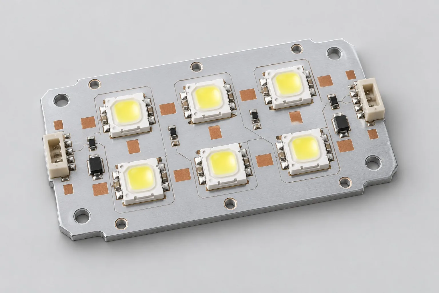
Aluminum-core LED design: for six series LEDs at example 700mA, list placement, IMS dielectric, and external current-driver interfaces, then heat sinks/interfaces/optical mounting. Measure board heating and complete optics separately. Existing heat sinks reduce mechanics work but do not eliminate installed thermal-path confirmation.
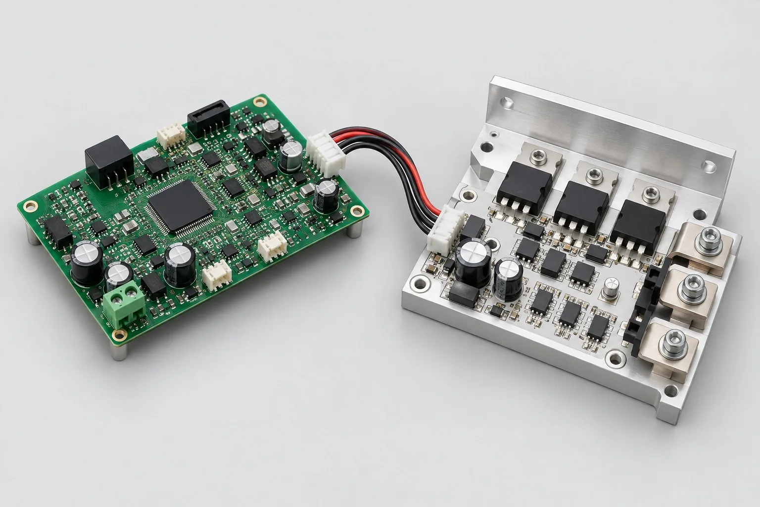
IMS thermal-board design: 24V/10A are targets. List IMS switches, FR-4 controls, short interconnects, and continuous-load/shutdown tests. Existing controllers reduce higher-level firmware work, but define sensing, overcurrent/temperature, and installed metal-enclosure heat paths. Metal area alone cannot price complete power controls.

Tell us the product use and which files are available. We can define the next engineering step even when the data package is not complete.