
Prototype Phase
Check acquisition, isolation, and drives using representative measurement ranges, bus cables, and loads; carry field reproduction conditions into pilot production.
Covering analog acquisition, isolated communication, and actuator drives, focus on field interfaces, noise isolation, power cooling, and long-term material maintenance.
Request Industrial Control Board Assembly →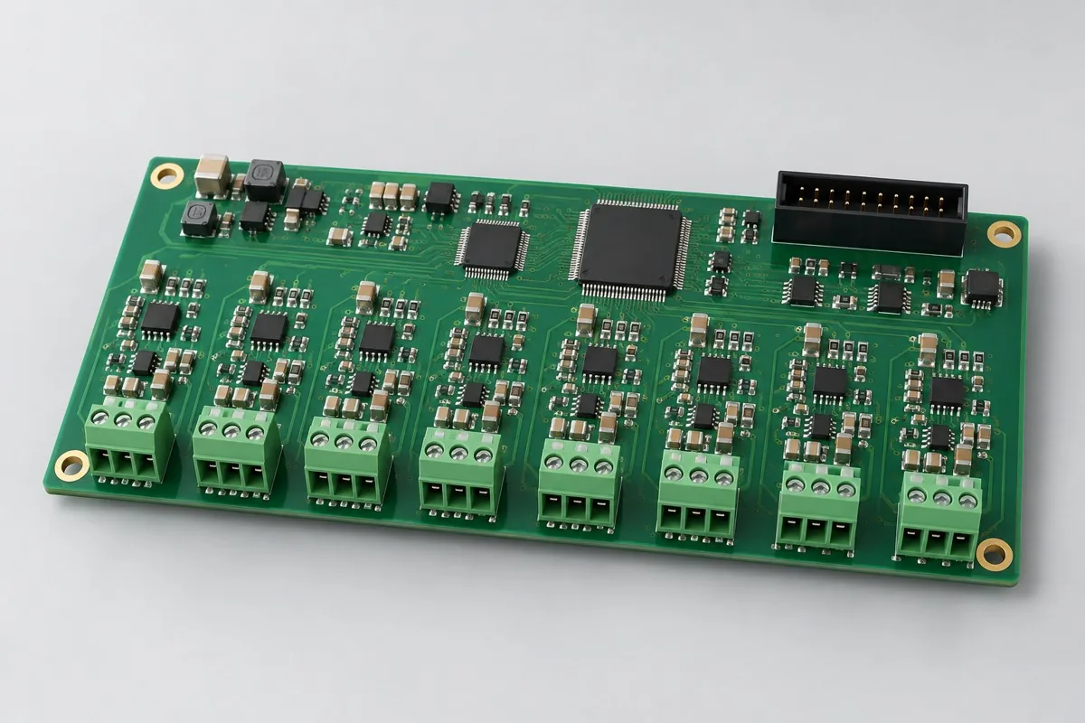
| Project Direction | PCB Manufacturing and Layout Focus | PCBA assembly and testing highlights |
|---|---|---|
| Multi-channel analog acquisition board | Signal return paths, analog/digital partitioning, input protection, and reference supplies | Multirange calibration, channel crosstalk, and abnormal-input protection |
| Isolated Industrial Communication Board | Isolation barriers, connector/shield grounding, differential traces, and protection components | Bus transmission/reception, baud rate, isolation testing, and disconnection recovery |
| Relay and motor driver board | High-current paths, copper weight and thermal paths, and terminal spacing | Loaded output, temperature rise, interlocks, reverse polarity, and protection operation |
| Review Items | What specific inputs are provided | How to confirm results |
|---|---|---|
| Field Interfaces | Analog ranges, digital levels, bus protocols, loads, and cable lengths | Create fixture-interface drawings and a channel/load test matrix |
| Harsh Environment | Temperature/humidity, dust, vibration, coating, and serviceable regions | Select materials and protective processes, and record environmental-validation and rework requirements |
| Product Lifecycle | Long-lead-time components, substitution lists, and firmware-revision strategy | Recheck interfaces, power consumption, footprints, and regression cases after changes |
Check acquisition, isolation, and drives using representative measurement ranges, bus cables, and loads; carry field reproduction conditions into pilot production.
Define multirange calibration, isolation, and protection cases; close coating, rework, and substitution impacts, and establish process and test revisions.
Deliver against the approved interface matrix, linking calibration data, materials, and firmware; run agreed regression cases for long-term substitution changes.
For industrial-control projects, in addition to Gerber, drill files, BOM, pick-and-place files/CPL, and assembly drawings, include operating environment, actual interfaces/loads, enclosure and harness drawings, target quantity, and the test limits above. If commissioning programming or calibration, add software revision, checksum, fixture wiring, and programming permissions.
Field-use and environmental validation require fixed mounting, cable, load, and protection conditions; agree separately on responsibility for service life and system certification.
View specific fabrication products by board-level task, or arrange a joint PCB fabrication and assembly review with complete information.
Engineering reference | QFN and SON assembly: thermal pads, printing, and solder joint verification: QFN/SON pad, stencil, and measured thermal process methods; not company capabilities.
Engineering reference | Packaging PCB fabrication files: units, layer order, and engineering notes: methods for PCB fabrication, hole layer spans, and file semantics.
| Work area | Inputs or responsibility | Expected output |
|---|---|---|
| Power and isolation | Supply range, grounding and isolation boundaries | Specify operating and abnormal conditions |
| I/O and buses | Interface levels, loads, timing and external wiring | Define interface tests and recovery behavior |
| Manufacturing | Assembly revision, programming and identification | Connect each unit or batch to the approved configuration |
| Acceptance | Test setup, pass/fail limits and records | Distinguish board tests from system qualification |
Use the project test scope to prepare the discussion. Unknown inputs should be listed as open questions; they do not authorize substitutions, omitted tests or unrecorded design changes.

Tell us the product use and which files are available. We can define the next engineering step even when the data package is not complete.