How is through-hole PCB assembly quoted? How are insertion and secondary soldering costs separated?
Quotes should separately itemize component lead forming and insertion, high-thermal-mass solder joint processing, fastening and insulation installation, and loaded checks for relays, power, and drives. Separate initial order setup costs from recurring batch and per-board costs. For the same quantity, also align revisions, delivery configuration, and tax and shipping terms to determine whether price differences reflect configuration or excluded work.
Quotation terms depend on the approved files, quantity, material supply, tests and delivery requirements.
Prepare a structured RFQ or use the short inquiry form.
How does complete through-hole PCB assembly differ from DIP soldering alone?
Complete through-hole PCB assembly includes function-related assembly and inspection; a standalone DIP order may cover only through-hole soldering. Compare wave, selective, or secondary soldering under the same component thermal tolerance, board accessibility, and quantity conditions.
How should loaded checks be selected for relay, power, and drive through-hole boards?
Relay boards require contact and load checks, power interfaces require terminal voltage drop checks, and drive boards require thermal and feedback checks. Matching hole and lead dimensions is only an assembly condition, not the complete basis for the board's load capacity.
Through-hole PCB assembly: order scope and acceptance
Through-hole PCB assembly serves boards with many relays, terminals, magnetic components, and power devices. First check hole-to-lead fit, component fastening, and thermal mass, then select wave or secondary soldering. Complete board delivery also requires defined circuit, load, and mechanical acceptance criteria.
Relay boards switch contacts, interface boards distribute power, and drive boards control inductive actuators. Their protection and test loads differ.
Differences in assembly and test paths
For relays, check hole fill/sealing compatibility; for interface boards, voltage drop/terminal temperature rise; for drive boards, heat dissipation and feedback. Review insertion height, secondary soldering heat, and fastening sequence separately.
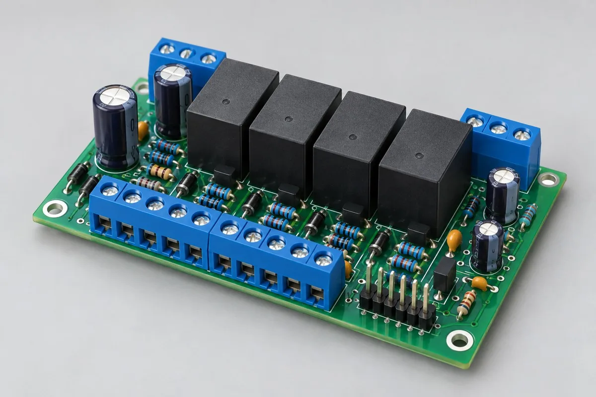
Relay Industrial Control Through-Hole Board
SMT first → relay/terminal insertion → soldering → functional test. Record wrong relay type, bridging, insufficient hole fill, and loose terminals separately. Acceptance includes de-energized and energized states; use channel states and load conditions instead of simply listening for relay clicks.
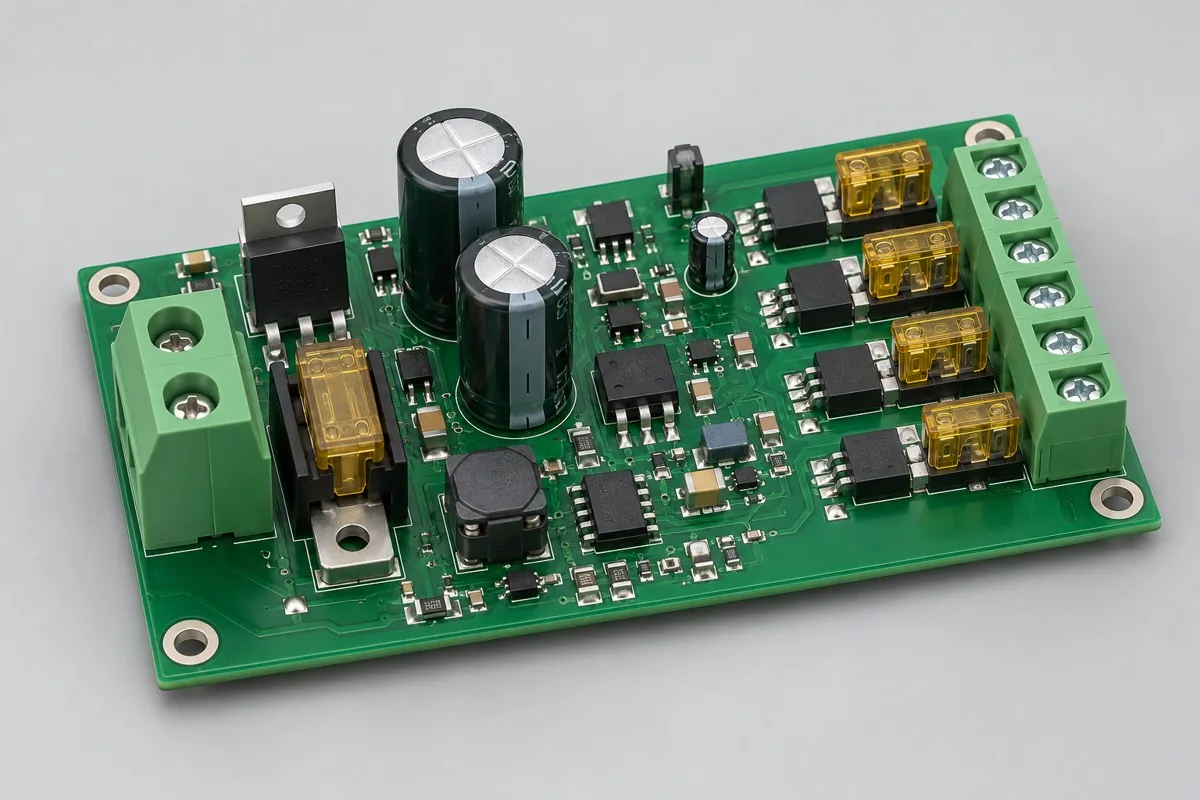
Power Connector Through-Hole Board
SMT → large-component insertion and soldering → cleaning → mechanical fastening → testing. A single power-on cannot exclude reversed capacitors, insufficient terminal soldering, or incorrect fuse types. Acceptance must check component polarity, rated selection, and loaded paths. Define voltage drop and temperature rise limits in the specification after design verification.
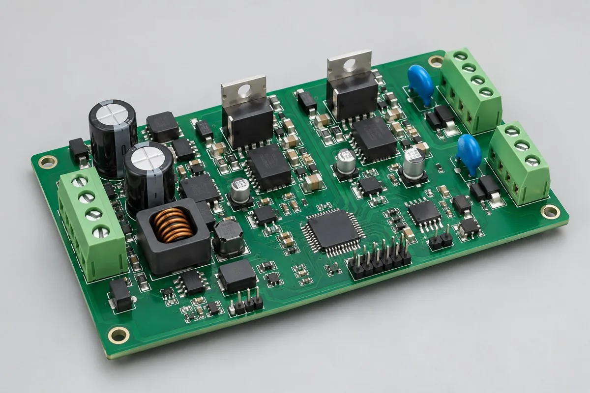
Device Driver Through-Hole Board
SMT → power component insertion → soldering → heat sink installation → load testing. Reversed components, poor solder joints, missing thermal insulation, and reversed feedback polarity can all appear temporarily normal at power-on. Acceptance must include protection operation and reset; repeat loaded testing after power-stage rework.
Ensure plug-in holes, pins, and post-install parts are kitted first
Provide physical lead/terminal specifications, polarity, lead trimming, and fastening requirements. Verify first articles separately for high-thermal-mass joints on relays, power terminals, and coil drives, then perform load testing after subsequent installation. Holes and leads: finished holes, lead dimensions, and protrusion requirements; do not infer solderability from bare board minimum holes. Soldering route: wave soldering, localized secondary soldering, or a mixed route, verified against component thermal tolerance and thermal mass.
Component supply, quantity and delivery
Define soldered wires, terminals, heat sinks, and external actuators as separate delivery configurations. Current capacity cannot be inferred from PCB copper weight.
For the order, align Gerber /BOM pick-and-place files/DNP and assembly drawings, quantity, customer-supplied/procured material lists, and firmware verification. Functional delivery includes circuit, load, state, and firmware testing, priced for the actual board and test setup. Confirm fees separately for stencil/carrier/fixture preparation, process operations, programming/calibration, and the supporting tests on this page. Agree on replenishment/attrition, excess materials, and change-related inventory first, then list delivery milestones after material readiness and scheduling are confirmed. Perform relevant regression testing for component/interface/mechanical/firmware changes, and record pilot issues separately from production release.
Material and Process Reference
Through-hole PCB assembly pricing and selection FAQ
How is through-hole PCB assembly quoted? How are insertion and secondary soldering costs separated?
Through-hole soldering can be estimated as board quantity × billable points per board × price per point + setup fee. A project-specific quotation requires review of the available files, quantity, materials, requested tests, delivery destination, taxes, shipping, and trade terms. This excludes materials, insertion, and functional testing. Any formula on this page organizes cost inputs; it is not a quoted rate.View cost items, calculation conditions, and sources.
How should I compare through-hole PCB assembly manufacturers' quotes?
First confirm whether delivery is a soldered board or an assembly with fastening, insulation, and load records. Define wave, selective, and secondary soldering scope by components and accessibility. Do not compare quotes by through-hole point count alone.
Does a terminal lead fitting into a hole mean the hole design is suitable?
Also check finished hole tolerance, lead envelope, board standoff, and fastening. Hole fit does not establish complete soldering of high-thermal-mass joints or terminal capacity for the specified load.
Are heat sinks and insulating pads included in through-hole assembly fees?
List installed parts, fastening, and insulation inspection against the mechanical BOM and drawings. Through-hole soldering alone differs from delivery with heat sink assemblies; a point price does not imply accessories are included.
Can a relay click serve as loaded acceptance?
Also check contact continuity, channel mapping, and power-off states. Specify resistive/inductive loads, inrush, and operating timing for loaded testing. Brief energization cannot replace life testing.
Why must voltage drop be retested after reworking a large terminal on a through-hole board?
Soldering and connection condition affect the loaded path. Retest using the original load, test points, and fastening conditions, and retain terminal and related net results. Do not release based only on shiny solder appearance.
Quote for through-hole PCBA assembly: describe the application, existing configuration, and expected quantity so we can discuss assembly inclusions and selection requirements.