How much does prototype PCB assembly cost? Are debugging and component changes assembly charges
Quotes should separately account for small-batch materials and stencils, first articles and assembly, firmware programming and basic testing, debugging, component changes, and dedicated fixture development. List initial-order setup charges separately from per-batch and per-board charges; for equal quantities, also align revisions, delivery configurations, and tax and freight terms to identify whether price differences reflect configurations or excluded work.
Quotation terms depend on the approved files, quantity, material supply, tests and delivery requirements.
Prepare a structured RFQ or use the short inquiry form.
What is the difference between bare PCB prototyping and prototype PCB assembly?
Bare PCB prototyping delivers boards without components; prototype PCB assembly also includes materials, assembly, and agreed firmware testing. Quote design debugging separately from manufacturing to approved files to avoid treating development rework as a fixed production operation.
Which functions should motor and communication PCB assembly prototypes verify first?
Motor prototypes first check drive, load, and protection; communication prototypes check ports, messages, and recovery. Define changes to verify in each round, record component modifications, then update the formal BOM and PCB.
Prototype PCB assembly: outsourcing and acceptance
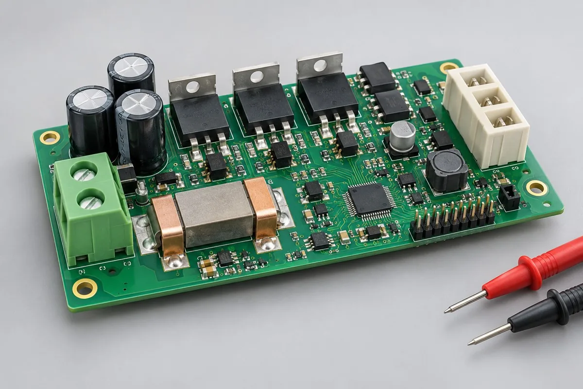
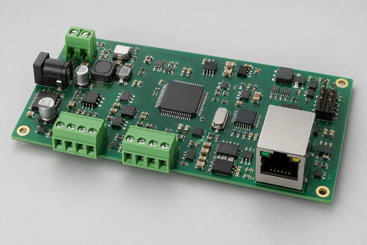
Prototype PCB assembly populates a bare board using the approved BOM, placement data and assembly drawings, delivering samples for the agreed debugging and verification tasks. Prototype SMT and trial assembly must preserve test points, permitted component changes, and firmware records; motor-drive and communication-interface samples separately verify loads, protection, or protocols. List bare PCB prototype fabrication and acceptance separately.
Motor samples need gate/phase-sequence/sensing/protection test points; communication samples need termination/messages/error recovery and interface variants.
Differences in assembly and test paths
Preserve debugging access during prototyping and record every component change; power up in energy-limited stages. Deliver issue records and waveforms/logs so the next revision can verify changes.
Motor driver validation prototype
SMT → subsequent power-component/terminal installation → staged power-up → energy-limited integration testing. Isolate bridge-arm shorts, gate ringing, sensing polarity, and phase-sequence errors by stage. Record acceptance against prototype verification objectives; rotation does not mean continuous-load, lifetime, and production-qualification validation is complete.
Communication interface validation prototype
SMT → subsequent interface soldering → test firmware → protocol integration testing. Isolate transmit/receive direction, termination, wire sequence, and protocol parameters separately. Record whether acceptance issues concern hardware or protocols, and rerun the same message set after firmware changes; do not deliver unmarked temporary jumpers that bypass unresolved issues.
Prototype Retention for Debugging Closed Loop
Define load/feedback/protection for motor samples and interfaces/termination for communication samples. Record component changes and jumper status by board identifier, use actual configurations in reports, and freeze debugging items and test firmware before volume production. Prototype tasks: power/control or interface/protocol verification objectives, with acceptance defined by actual functions. Inputs: approved Gerber/BOM/CPL and assembly drawings; address missing design-development items separately.
Component supply, quantity and delivery
Separate prototype and debugging firmware from final shipping firmware; freeze the BOM, parameters, test points, and repeatable fixtures before volume production.
For orders, align Gerber/BOM/CPL/DNP and assembly drawings, quantities, consigned/procured material lists, and firmware verification. Deliverables include physical samples, firmware, measurements/issues, and change lists; complete-product certification is not included by default. Confirm stencil/carrier/fixture preparation, assembly operations, programming/calibration, and supporting tests on this page as separate charges. Agree replenishment/loss allowances, surplus materials, and inventory affected by changes in advance; list delivery milestones after material readiness and scheduling are confirmed. Regression-test component/interface/structure/firmware changes against the relevant tests, and record prototype issues separately from production release.
Material and Process Reference
- Engineering reference | SMT packages and assembly methods: pads, stencils, and thermal processes: a package/assembly method index only; not evidence that the product configurations on this page are models produced by KFPCBA
Prototype PCB assembly pricing and selection FAQ
How much does prototype PCB assembly cost? Are debugging and component changes assembly charges
For standard placement, first calculate board quantity × billable points per board × price per point + setup fee. A project-specific quotation requires review of the available files, quantity, materials, requested tests, delivery destination, taxes, shipping, and trade terms. This is a placement-only reference; bare PCBs, materials, and testing are charged separately. Any formula on this page organizes cost inputs; it is not a quoted rate.View cost items, calculation conditions, and sources.
How should I compare quotations from prototype PCB assembly suppliers?
Separate manufacturing to files from design debugging, and check prototype quantities, materials, programming, and rounds of component changes. Motor prototypes need load protection; communication prototypes need message and recovery records. The statement that samples were tested cannot replace a defined scope.
Do PCB assembly samples manufactured to files include design component changes?
Manufacturing follows the approved BOM/PCB; signal-conditioning, algorithm, or drive changes are separate engineering tasks. Update files with each round of component changes before reviewing the next sample scope.
If firmware already exists for prototyping, is test development still needed?
Writing a binary does not define test stimuli or limits. Provide power supplies, counterpart devices, or loads and clarify who prepares supporting equipment; separate programming verification from functional execution.
Can procurement be expanded once a motor prototype rotates without load?
No-load operation covers only some behavior; controlled loads, phase-sequence/sensing checks, and protection still require approved test cases. Resolve key risks before freezing power components and thermal design; more boards do not replace verification.
How should production files handle jumper wires left on communication prototypes?
Check message/recovery results against the actual jumper-wire revision, then determine whether to update the circuit, PCB, or firmware. The formal manufacturing package must not reference uncorrected old drawings; confirm supporting items against the new revision.
What do first-article photos, physical first articles, and first-article reports each provide?
Photos support remote checks of positions, orientations, and visible assembly, but cannot show hidden solder joints or every function. Physical sample approval requires agreement on sample revisions, quantities, shipping, and customer test responsibilities; first-article reports list actual inspection methods, results, and issue-closure records. List production, inspection, and logistics scope separately for each; a photo cannot replace report or sample acceptance.
Consult PCBA for Prototyping Quotes: describe the application, existing configuration, and expected quantity so we can discuss assembly inclusions and selection requirements.