How is energy storage PCB assembly quoted? How do BMS and power interfaces differ?
Quotes should separately itemize AFE, isolation and protection materials, sensing connections and cleaning, cell simulation or bus signal fixtures, calibration, balancing, and precharge state testing. Separate initial order setup costs from recurring batch and per-board costs. For the same quantity, also align revisions, delivery configuration, and tax and shipping terms to determine whether price differences reflect configuration or excluded work.
Quotation terms depend on the approved files, quantity, material supply, tests and delivery requirements.
Prepare a structured RFQ or use the short inquiry form.
How does a BMS sensing board differ from an energy storage power interface board?
BMS sensing boards handle cell and temperature signals, while power interface boards handle the bus, precharge, and contactor feedback. They require different simulated sources and verification states. Low-energy board-level testing is not high-energy full-pack testing.
Should energy storage PCB assemblies be selected by series cell count or bus precharge requirements?
First select the BMS by series cell count, sensing measurement range, and balancing method, then select the interface by bus, contactors, and precharge strategy. Implement system protection requirements in every relevant state and its records.
Energy storage PCB assembly: order scope and acceptance
Energy storage module PCB assembly distinguishes per-cell BMS sensing from power interface control. The former checks sensing wire order, calibration, and balancing; the latter checks precharge, contactor feedback, and bus monitoring. Agree separately on low-energy board-level testing and high-energy full-pack verification.
Sensing boards: series cell count, AFE, temperature, and balancing; interface boards: bus monitoring, precharge states, contactor feedback, and fault exit.
Differences in assembly and test paths
Start with low-energy cell/bus simulation before approved system verification. Test per-channel calibration and precharge timing separately. High-energy faults are not automatically part of brief outgoing tests.
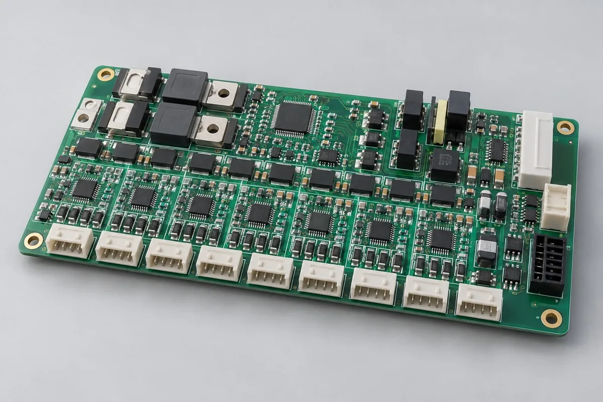
Energy Storage BMS Sampling Control Board
SMT → secondary sensing socket soldering → cleaning inspection → simulated cell testing. Incorrect AFEs, sensing solder bridges, wrong wire order, and incorrect thresholds are critical defects. Acceptance must cover each channel including boundary states; a normal total voltage reading does not verify every cell. Recalibrate after rework and check the balancing-off state.
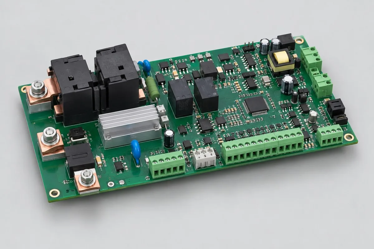
Energy Storage Power Interface Board
SMT → secondary interface soldering → cleaning/insulation inspection → low-energy testing. Assess wrong divider values, reversed contactor signals, and skipped precharge independently. Acceptance focuses on maintaining a safe state during failure. One normal closure does not establish that all fault handling passes.
Cell simulator and precharge load separated
For BMS sensing boards, first define series cell count, sensing wires, and protection parameters. For power interface boards, first define contactors, precharge, and bus measurement range. Board-level records, full-pack safety, and system integration each have their own scope and cannot replace one another. Sensing inputs: series cell count, wire order, measurement range, temperature, and balancing strategy, with channels verified using approved simulated sources. Power interfaces: precharge, drive, feedback, and bus monitoring, with main power circuit delivery scope listed separately.
Component supply, quantity and delivery
Define delivery boundaries for batteries/busbars/contactors/harnesses, and list power system certification and safety verification as independent scopes.
For the order, align Gerber /BOM pick-and-place files/DNP and assembly drawings, quantity, customer-supplied/procured material lists, and firmware verification. Delivery records include calibration, state machines, wiring tables, and board-level testing; they do not replace full energy storage pack verification. Confirm fees separately for stencil/carrier/fixture preparation, process operations, programming/calibration, and the supporting tests on this page. Agree on replenishment/attrition, excess materials, and change-related inventory first, then list delivery milestones after material readiness and scheduling are confirmed. Perform relevant regression testing for component/interface/mechanical/firmware changes, and record pilot issues separately from production release.
Material and Process Reference
Energy storage module PCB assembly pricing and selection FAQ
How is energy storage PCB assembly quoted? How do BMS and power interfaces differ?
For standard placement, first calculate board quantity × billable points per board × price per point + setup fee. A project-specific quotation requires review of the available files, quantity, materials, requested tests, delivery destination, taxes, shipping, and trade terms. This is a placement-only reference; bare PCBs, materials, and testing are charged separately. Any formula on this page organizes cost inputs; it is not a quoted rate.View cost items, calculation conditions, and sources.
How should I compare energy storage module PCB assembly manufacturers' quotes?
For BMS RFQs, fix series cell count, calibration, and balancing. For interface boards, fix bus signals, contactors, and precharge states. Quote low-energy simulation testing separately from full-pack tests. Different test levels cannot be compared directly by total price.
What test conditions are still needed when a BMS RFQ specifies series cell count?
Provide AFE, actual series cell count, temperature inputs, balancing, and thresholds. Accept each item under approved cell simulation conditions. Series cell count defines a design revision, not a production line capability commitment.
What states must be provided for an energy storage interface board precharge test?
Define main/precharge contactors, feedback, bus simulation, and fault lockout timing. Separate responsibilities for low-energy setups and high-energy full-pack tests. No-load actuation does not establish system acceptance.
Can testing be removed from the quote if the sensing harness is customer-supplied?
Customer supply changes procurement boundaries, but wire order, mistake-proofing, and per-channel mapping still require checks on the actual harness. A harness change requires terminal and sensing confirmation; identical sockets alone do not establish compatibility.
Why should an AFE substitution be priced beyond the material difference alone?
Check effects on input range, package, firmware, and calibration. After BOM approval, reconfirm per-cell sensing, temperature, and balancing. Design adaptation and production programming are different work.
Quote for energy storage module PCBA: describe the application, existing configuration, and expected quantity so we can discuss assembly inclusions and selection requirements.