What adds cost to rigid-flex PCB assembly? Are carriers charged separately?
Quotes should separately itemize flexible boards and materials, rigid-area placement support, forming and enclosure fastening, and post-bend image or sensor calibration testing. Separate initial order setup costs from recurring batch and per-board costs. For the same quantity, also align revisions, delivery configuration, and tax and shipping terms to determine whether price differences reflect configuration or excluded work.
Quotation terms depend on the approved files, quantity, material supply, tests and delivery requirements.
Prepare a structured RFQ or use the short inquiry form.
How does placement-only rigid-flex PCB assembly differ from formed and enclosed delivery?
Placing components only on rigid areas differs from delivering a formed assembly. Carriers must support the board and protect flex areas. Normal board-level function cannot replace post-enclosure retesting. Quotes should distinguish delivery shapes.
How should post-bend retesting be selected for rigid-flex camera and sensor assemblies?
Camera connections require image and latch checks; sensor assemblies require calibration and board stress checks. Define mechanical cycles separately for dynamic bending. A bend for fixed installation cannot be used directly for repeated movement.
Rigid-flex PCB assembly: order scope and acceptance
Rigid-flex PCB assembly requires joint review of rigid-area placement, flex-area support, fixed bends, and enclosed functionality. Camera connections and portable sensors have different interface/calibration tasks. Historical bare board examples cannot replace evidence for current assembly processes and dynamic service life.
Camera assemblies: image interfaces/fixed bends; sensor assemblies: calibration/board stress/enclosure-induced offset. Review dynamic bending requirements independently.
Differences in assembly and test paths
Carriers support rigid areas and protect flex areas. Establish board-level, post-forming, and post-enclosure checkpoints; normal function before bending does not establish final function.
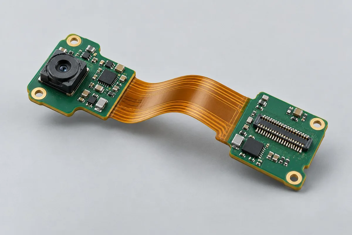
Rigid-Flex Camera Connection Component
Carrier-supported rigid-area SMT → interface inspection → formed assembly → image testing. Assess flex-area scratches, fractured copper paths, damaged latches, and incorrect fastening points separately. Acceptance follows the assembled image and mechanical condition. If dynamic life is required, define cycles, loads, and criteria separately.
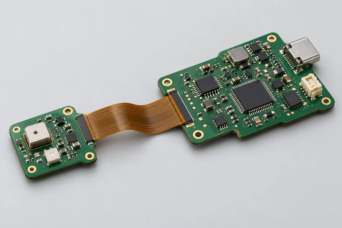
Rigid-Flex Portable Sensor Component
Carrier-supported dual-area SMT → calibration → forming → enclosed retesting. Handle sensor offset, flex-area cracking, misaligned stiffeners, and battery wiring errors separately. Acceptance includes post-forming/enclosure data. Normal board-level calibration cannot exclude mechanically induced offset.
Flexible zone stress and delivery posture
Submit fixed bend shapes, flex-area no-clamp zones, stiffeners, and module/connector drawings. Confirm reflow carriers and installation carriers separately. Agree separately on pre-bent delivery and dynamic bending requirements; product names do not establish service life. Mechanical inputs: rigid-flex outline, stackup, stiffeners, and fixed bend radius, formed to approved drawings. Assembly support: carrier contact, no-clamp zones, and component thermal tolerance in both areas, without pressing flex areas or sensitive sensors.
Component supply, quantity and delivery
Control stiffeners, fastening points, forming drawings, and anti-bending packaging. Do not prefill uniform bend counts and radii.
Provide Gerber files, the BOM, pick-and-place files, do-not-populate (DNP) information, assembly drawings, quantity, customer-supplied and procured material lists, and firmware verification requirements under one order revision. Service life boundaries include separate verification of static installation and dynamic bending, without applying historical thermal cycle figures. Confirm fees separately for stencil/carrier/fixture preparation, process operations, programming/calibration, and the supporting tests on this page. Agree on replenishment/attrition, excess materials, and change-related inventory first, then list delivery milestones after material readiness and scheduling are confirmed. Perform relevant regression testing for component/interface/mechanical/firmware changes, and record pilot issues separately from production release.
Material and Process Reference
Rigid-flex PCB assembly pricing and selection FAQ
What adds cost to rigid-flex PCB assembly? Are carriers charged separately?
For standard placement, first calculate board quantity × billable points per board × price per point + setup fee. A project-specific quotation requires review of the available files, quantity, materials, requested tests, delivery destination, taxes, shipping, and trade terms. This is a placement-only reference; bare PCBs, materials, and testing are charged separately. Any formula on this page organizes cost inputs; it is not a quoted rate.View cost items, calculation conditions, and sources.
How should I compare rigid-flex PCB assembly manufacturers' quotes?
Check carrier protection for flex areas, formed fastening, and post-enclosure retesting. Camera images and sensor calibration require different external setups. Bare board testing prices cannot represent assembly delivery in the final installed shape.
Are rigid-flex placement carriers and forming tools the same tooling?
Placement carriers support rigid areas and protect flex areas; forming tools define final bend angles and fastening. Agree separately on fabrication, customer supply, storage, and reuse, with per-unit assembly execution charged separately.
Why retest sensors after calibration and enclosure installation?
Enclosure pressure, fastening, and connections can change readings. Fix the actual installation revision and check before/after deviations, sleep, and communication. Bare board calibration does not cover final mechanical stress.
Is continuity acceptance alone enough for a rigid-flex camera assembly?
Continuity must also be linked to the image path, FPC latch, and static forming. Specify the camera module and processing endpoint, and retain image/fault records after assembly.
Can a quote for a fixed-installation rigid-flex assembly include dynamic bending?
Provide radius, path, cycles, and criteria separately for repeated movement. Static bend references do not establish service life. Review mechanical setups and cycle verification independently.
Request a rigid-flex PCB assembly quote: describe the application, existing configuration, and expected quantity so we can discuss assembly inclusions and selection requirements.