
Prototype Phase
Check connectors and harnesses, cold startup, and supply disturbances on representative boards; use agreed conditions for BMS sampling or loaded tests.
For board-level projects such as displays, diagnostic communication, and power management, review temperature/vibration, supply transients, heavy-copper cooling, and interface testing separately.
Request Automotive Board Assembly →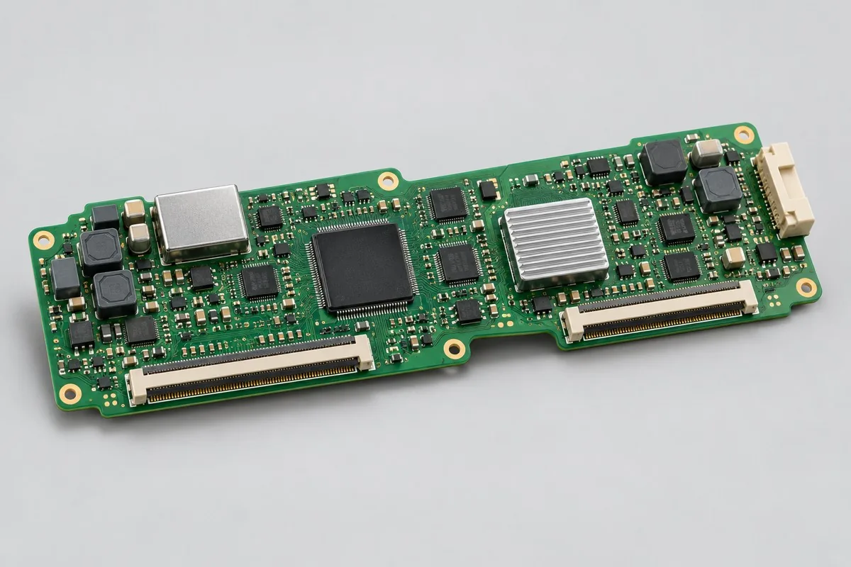
| Project Direction | PCB Manufacturing and Layout Focus | PCBA assembly and testing highlights |
|---|---|---|
| Display and diagnostic communication board | Interface impedance, ESD component positions, connector stress, and pad anchoring | Test interfaces such as CAN/LIN using actual ICs and software; cold startup and power-loss recovery |
| BMS acquisition board | Cell sampling, isolation boundaries, leakage paths, and balancing-resistor thermal distribution | Per-channel analog input, open-wire detection, communication, insulation, and traceability |
| Power and actuator control board | Copper weight/trace-spacing combinations, power-device pads, vias, and thermal interfaces | Temperature rise, protection operation, startup/shutdown, and fault feedback under specified loads |
| Review Items | What specific inputs are provided | How to confirm results |
|---|---|---|
| Installation Environment | In-vehicle/exterior location, temperature, vibration, and supply-disturbance conditions | Responsible parties sign off board-level testing and vehicle-system validation separately |
| Production Management | Critical characteristics, change approval, supplier and PPAP document lists | Maintain consistency among materials, fabrication revisions, and critical-characteristic measurement records |
| Connections and heat dissipation | Harness tension, mating direction, power-device thermal paths, and heatsink tolerances | Recheck solder joints, assembly stress, and loaded temperature rise after trial installation |
Check connectors and harnesses, cold startup, and supply disturbances on representative boards; use agreed conditions for BMS sampling or loaded tests.
Close thermal-process, assembly-stress, and critical-characteristic issues; confirm substitution approvals, test software, and customer-required document lists.
Maintain approved revisions, material batches, and critical-characteristic records; use separate criteria for board-level release and vehicle-installation validation.
For automotive electronics projects, in addition to Gerber, drill files, BOM, pick-and-place files/CPL, and assembly drawings, include operating environment, actual interfaces/loads, enclosure and harness drawings, target quantity, and the test limits above. If commissioning programming or calibration, add software revision, checksum, fixture wiring, and programming permissions.
Sign off board-level power, interface, and environmental tests separately from vehicle validation; follow approved documents for customer special characteristics and change requirements.
View specific fabrication products by board-level task, or arrange a joint PCB fabrication and assembly review with complete information.
Engineering reference | QFN and SON assembly: thermal pads, printing, and solder joint verification: QFN/SON pad, stencil, and measured thermal process methods; not company capabilities.
Engineering reference | Packaging PCB fabrication files: units, layer order, and engineering notes: methods for PCB fabrication, hole layer spans, and file semantics.

Tell us the product use and which files are available. We can define the next engineering step even when the data package is not complete.