
24V constant-current LED driver control board design
Use buck conversion when total LED voltage drop is below the input with sufficient control headroom; higher-voltage strings require boost/buck-boost selection again.
Select LED boards/drivers for single-channel constant current, tunable white, or RGBW; design voltage headroom, current, dimming, and thermal management, and calibrate acceptance using actual LEDs and optical structures. LED design addresses current, color mixing, and thermal conditions together. Distinguish driver control boards from LED boards first, then select dimming and protection methods.
Configurations in this category support development requirements discussions. Actual components, structures, and performance are confirmed in the project revision; historical development directions and engineering references are identified separately.
This category covers constant-current lighting, tunable white, and RGBW color mixing. Costs are broken down by schematic, PCB layout, agreed software, and prototype validation scope; the main workload differences involve current drive, LED-group layout, dimming software, and optical/electrical/thermal validation. Layer count, board area, or channel count alone cannot determine development pricing; the usability of existing files and test conditions also affect the effort.
Quotation terms depend on the approved files, quantity, material supply, tests and delivery requirements.
Prepare a structured RFQ or use the short inquiry form.
| Quotation Items | What services are included | What to Check When Comparing Quotes |
|---|---|---|
| Existing circuit layout | Implement layout using approved schematics, footprints, and mechanical design | Whether schematic review, stackup/constraints, and fabrication files are included |
| From functional R&D | Current drive, LED-group layout, dimming software, and optical/electrical/thermal validation | Whether circuits, firmware, and validation targets are complete |
| Prototypes and revisions | Build prototypes from the frozen design, record test feedback, and release a controlled revision | Whether prototype quantity, component procurement, and change scope use the same basis |
Constant current starts by matching LED strings; tunable white mixes warm and cool white; RGBW adds color and white channels. Select by LED connections, color tasks, and dimming requirements, then compare driver, software, and optical-calibration costs.
Start selection with series/parallel arrangement, LED voltage drops, channel count, minimum brightness, and color settings, then review the parameters, cost boundaries, and validation conditions of the specific designs below.
| Review Questions | Why it impacts design | How to select and close |
|---|---|---|
| Drivers and light boards | The control board regulates current; the LED board determines LED arrangement and thermal paths. | Freeze the interface between them first, and compare constant-current topology, voltage headroom, and cable voltage drop. |
| Dual-color temperature and RGBW | Current ratios in mixing channels differ from optical output ratios. | Agree on measurement positions, LED batches, and calibration methods; PWM duty cycle alone cannot predict color. |
| Dimming and Thermal Management | Low brightness, flicker, and sustained high power all require review. | Define dimming-frequency and resolution targets, and check startup, thermal derating, and short/open-circuit protection. |
LED series/parallel configuration, Vf range, current targets, supply, brightness/color-temperature basis, dimming interfaces, and cooling structure.
| Current Stage | Customer-Supplied Materials | Design deliverables |
|---|---|---|
| Functional requirements only | LED series/parallel configuration, Vf range, current targets, supply, brightness/color-temperature basis, dimming interfaces, and cooling structure. | Functional/state requirements, approach comparison, mechanical design, and open items for constant-current dimming, tunable white, and RGBW |
| Existing schematics or PCB | Editable circuit/PCB files, BOM, and mechanical design for products in this category; include LED series/parallel configuration, Vf range, current targets, supply, brightness/color-temperature basis, dimming interfaces, and cooling structure. | LED/driver configuration, current and thermal budgets, dimming state table, and optical/electrical test records |
| Existing prototype pending revision | Fault reproduction conditions, raw logs/waveforms, test equipment, and original board revision | Troubleshoot faults related to constant-current dimming, tunable white, and RGBW, and deliver revised files, an impact list, and regression records under the same operating conditions |
Use buck conversion when total LED voltage drop is below the input with sufficient control headroom; higher-voltage strings require boost/buck-boost selection again.
Separate boards move driver heat outside the optical region; a single board reduces wiring but requires LED thermal-coupling assessment.
Different LED colors have different voltage drops; calculate driver operating headroom and cooling separately.
LED/driver configuration, current and thermal budgets, dimming state table, and optical/electrical test records. Link deliverables to the same requirements revision; the PCB fabricator confirms materials, stackup, holes, and fabrication conditions, while PCB assembly checks footprints, soldering, programming, and test points. Recheck this category's constraints after critical-component substitutions or mechanical changes.
Key validation in this category: channel current, dimming and color mixing, startup/protection, optical conditions, and temperature rise.
| Acceptance Stage | Conditions to be frozen | Report Records |
|---|---|---|
| Functionality and boundaries | Component/software revisions, supply/load, and interface or mechanical operating conditions | Test procedures, raw logs/waveforms, results, and abnormal states |
| Application-specific performance | Channel current, dimming and color mixing, startup/protection, optical conditions, and temperature rise | Instruments and calibration, environment, samples, criteria, and exclusions |
| Version Closure | Change list, permitted limitations, passed items, and open items | Fabrication and software packages, test reports, and issue-closure records |
Constant current starts by matching LED strings; tunable white mixes warm and cool white; RGBW adds color and white channels.
First specify series/parallel arrangement, LED voltage drops, channel count, minimum brightness, and color settings.
Layout-only work can be discussed when usable schematics and component information exist. Starting from constant-current lighting, tunable-white, or RGBW color-mixing requirements requires selection and circuit design first. Itemize software, prototypes, and testing separately; do not treat layout fees as a complete development budget.
For constant-current drivers, list LED strings, current, and faults; for tunable white, warm/cool mixing and calibration; for RGBW, four-channel mapping and concurrent thermal conditions. Assign responsibility separately for LED-board layout, external power supplies, and optics. Basic current operation and color-temperature/color deliverables cannot be combined into a vague unit price.
Provide series LED count, voltage drop, current, supply, and optical positions for each group, and confirm a constant-current or constant-voltage architecture. Layout implements switching loops and thermal paths; conduct circuit review first if LED strings and cooling are unresolved. A 24V label alone does not establish suitability for any LED group.
Dimming handles PWM/interfaces and settings; calibration converts actual warm/cool or RGBW LED-group measurements into mappings. Existing customer control software can reduce interface development, but calibration tables still depend on LED batches/optics and temperature. Phone-based scenarios and cloud services are not automatically included in LED-board quotations.
Retain LED part numbers/batches, series connections, current/temperature, and optical positions, and include driver calculations with circuit/PCB files. Deliver mappings and derating parameters for commissioned software; record minimum brightness, color/illuminance, and thermal conditions in reports. LED replacements require more than matching pad dimensions.
Add power stages, interfaces, concurrent power delivery, and thermal requirements, then reassess mapping and optical tasks. Evaluate retaining the original control protocol, and list new prototype tests separately. Changing two channels to four does not necessarily double all prior development costs, nor is it merely a minor change involving a few extra components.
Low-voltage drivers and LED boards are separate work from mains-input power supplies/complete-unit insulation. LED-group and dimming-interface conditions may remain; define input conversion, safety, and complete-unit validation separately. Low-voltage references in this category do not imply direct-mains design or certification is included.
Initially describe the product task, application, and current files. A formal quotation should confirm LED series/parallel configuration, Vf range, current targets, supply, brightness/color-temperature basis, dimming interfaces, and cooling structure. If source files exist, provide circuit/PCB/BOM and mechanical revisions together; if prototypes exist, include fault conditions. First identify frozen functions and structures, then compare circuit, layout, software, and validation work; unresolved items must not be assumed to share the same service scope.
Key validation in this category: channel current, dimming and color mixing, startup/protection, optical conditions, and temperature rise. For each RFQ item, specify the actual load/interface or structure, prototype quantity, measurement method, equipment, and permitted deviation; deliver raw results, anomalies, and revision closure separately. Circuit/PCB checks and complete-unit functional validation are different tasks; a quotation including only the former does not justify omitting the performance measurements specific to this category.
Select and place components using the manufacturer information in the specific design details, and record file revisions and applicable conditions with the project; the company's historical development directions do not mean the reference designs on this page have been delivered in volume.
Return to the electronics design technical section · PCB Manufacturing · PCB assembly · Submit R&D requirements. When requesting LED PCB design, prepare functions, interfaces, board outline, and existing design information.
Send the product functions, interfaces, mechanical constraints, available files, and required development stage. Compare design capability scope and development support before defining deliverables.
Compare reference designs by function, interfaces, and mechanical constraints, including design tradeoffs and prototype-acceptance methods.
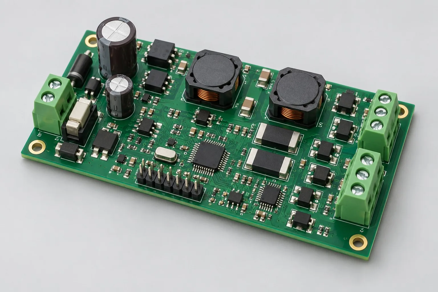
Constant-current LED driver design: freeze 24V input, string drops, and 350mA or 700mA settings. Baseline work covers the constant-current stage and faults. List PWM/analog dimming, MCU temperature readback, and low-brightness verification separately. Identify existing LED boards/heat sinks by revision rather than pricing complete luminaire development by channel count.
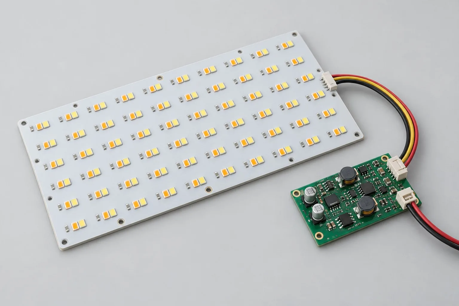
Tunable-white LED design: a two-channel 350mA example baseline drives warm/cool independently; mixing adds mappings and actual LED/diffuser calibration. List optical calibration, thermal drift, and illuminance uniformity by measurement conditions. Two-PWM pricing is not complete color-temperature delivery.
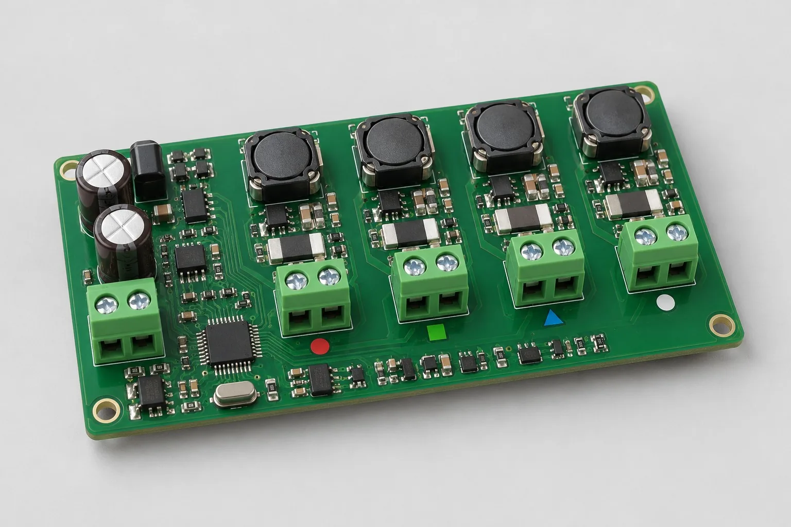
Define a four-channel RGBW constant-current board from the actual LED wiring, forward voltages, and optical targets. Review current control, scene firmware, color calibration, concurrent thermal load, and fault transitions.

Tell us the product use and which files are available. We can define the next engineering step even when the data package is not complete.