
TOPIC FOCUS
Treat insertion and soldering as one controlled route
The assembly drawing should identify polarity, seating, lead-form rules, solder access, keep-outs, fixtures, manual operations, inspection points, and test requirements.
Through-hole assembly planning should define insertion orientation, lead preparation, soldering route, thermal exposure, heavy-part retention, masking, inspection, cleaning, and post-process testing.
The assembly drawing should identify polarity, seating, lead-form rules, solder access, keep-outs, fixtures, manual operations, inspection points, and test requirements.
A through-hole designation does not select wave, selective, or manual soldering by itself. Component geometry, board layout, heat sensitivity, side clearance, and acceptance criteria determine the route.
Use this topic-specific checklist with the linked engineering reference. Record the actual project conditions and the agreed acceptance scope.
| Decision | Input to confirm | Record to retain |
|---|---|---|
| Insertion | Orientation, lead form and seating height | Assembly drawing and fixture notes |
| Soldering | Wave, selective or manual access and heat limits | Chosen route and masking needs |
| Release | Joint inspection and functional checks | Acceptance record after soldering |
These records provide context for the topic. They do not replace review of the current files, materials, quantities, tests, or acceptance conditions.
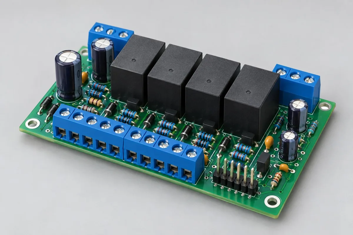
Relay control board through-hole assembly pricing depends on relays, terminals, control interfaces, and load conditions. Compare insertion, soldering, fastening, programming, and actuation-test scope; distinguish board-level checks from external-load verification, and check material supply and lot records.
A relay-control assembly reference for discussing inserted parts and solder access.View Configuration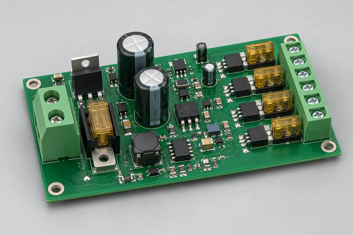
Power interface board through-hole assembly reference configurations cover power distribution, polarity protection, and branch fusing. Separate SMT, large-component through-hole soldering, cleaning, mechanical fastening, and testing; compare material supply, setup, and per-lot assembly costs. Check branch continuity, protection direction, voltage-drop, and thermal-distribution test scope, plus interface board + branch definitions + material lots + load-record deliverables.
A power-interface plug-in reference for lead preparation and through-hole routing.View Configuration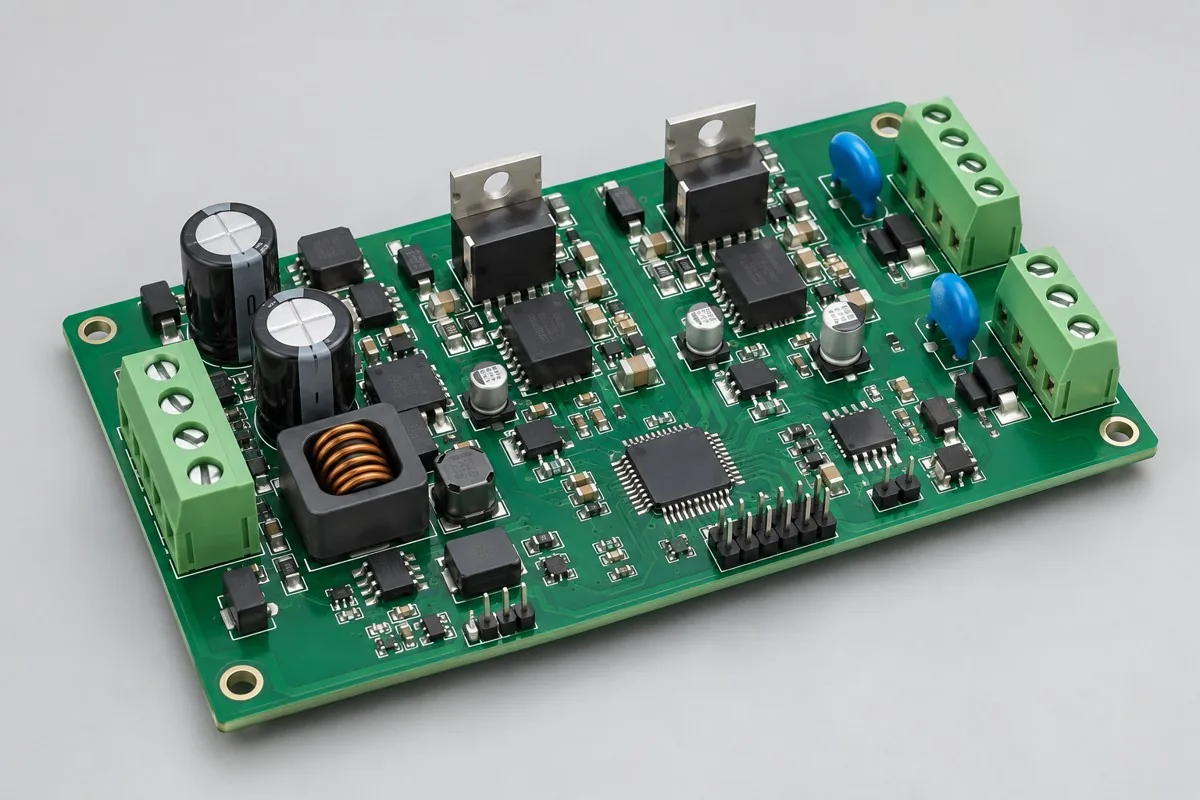
Review through-hole assembly for an equipment driver board with coil or actuator outputs. Define power devices, insulation, heatsink installation, feedback, firmware, and loaded protection tests in the RFQ.
A driver-board plug-in reference for mixed assembly and post-solder checks.View Configuration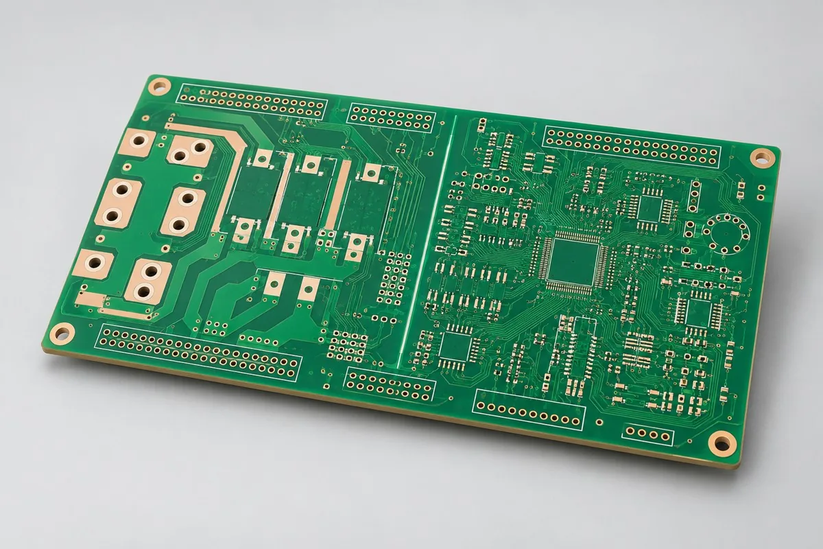
Six-layer inverter control boards: review power and sensing nets, terminal holes, isolation slots, and copper inspection. All values are illustrative; approve fabrication drawings and acceptance criteria before ordering. Assembly and system verification require separate scope.
A fabricated control-board reference for reviewing hole and land requirements before assembly.View Configuration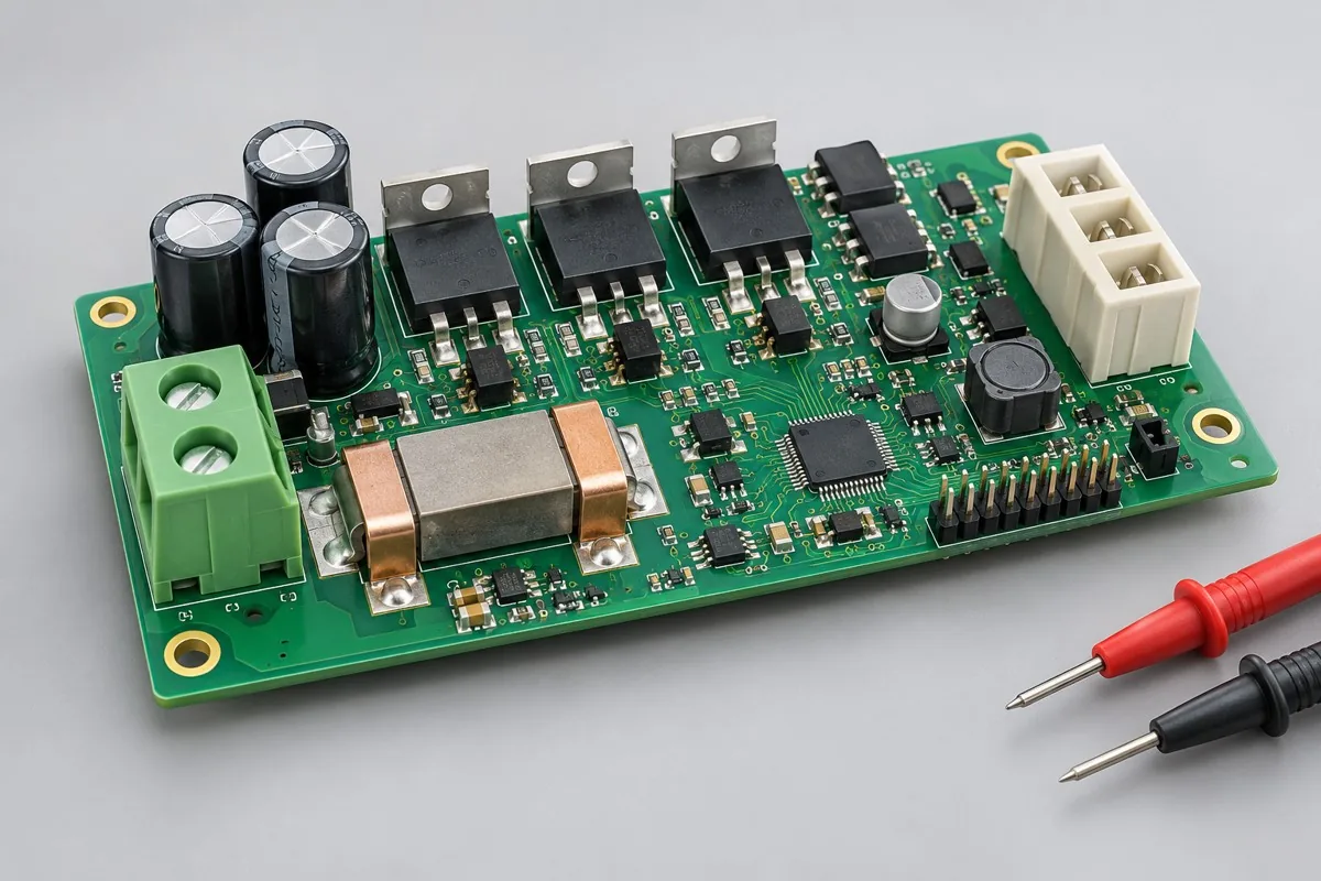
Motor driver prototype assembly references cover three-phase drives and current/position-feedback checks. Compare materials, SMT, later-installed power parts, staged power-up and energy-limited testing. Define gate, phase-sequence, sampling, controlled-load and protection tests, and retain measurement records and component-change revisions.
A motor-driver PCBA reference where heavy or heat-sensitive parts may need route review.View ConfigurationUse this reference to check the essential inputs, then continue to the articles for specific methods and exceptions.
Compare through-hole insertion, wave soldering, and later soldering operations using lead-to-hole fit, component thermal limits, process routing, and final inspection requirements.
Read Topic ReferenceFive articles are shown per page, newest first. Page 1 of 1.
Compare related decisions. Browse all engineering topics
Share the available fabrication files, BOM, drawings, quantities, target schedule, test scope, and acceptance requirements. The response will be based on the actual project conditions.

Tell us the product use and which files are available. We can define the next engineering step even when the data package is not complete.