
High voltage bus isolation sampling board design solution
A small-range isolation amplifier for a shunt channel cannot directly serve a high-voltage divider channel. Select the two front ends separately.
Distinguish high-voltage bus sensing from power system control interfaces. Design by measurement range, insulation conditions, and failure states, delivering isolation boundaries, budgets, and approved test records. High-voltage design centers on isolated sensing and control interfaces. Establish insulation coordination and fail-safe boundaries before selecting components and layout.
Configurations in this category support development requirements discussions. Actual components, structures, and performance are confirmed in the project revision; historical development directions and engineering references are identified separately.
This category covers isolated bus sensing and power control interfaces. Split costs by schematic, PCB layout, agreed software, and prototype verification scope. Key work differences involve input conditioning, insulation coordination, isolated power, and error/fault testing. Layer count, board area, or channel count alone cannot determine development pricing. Usability of existing files and test conditions also affect effort.
Quotation terms depend on the approved files, quantity, material supply, tests and delivery requirements.
Prepare a structured RFQ or use the short inquiry form.
| Quotation Items | What services are included | What to Check When Comparing Quotes |
|---|---|---|
| Existing circuit layout | Implement layout using approved schematics, footprints, and mechanical design | Whether schematic review, stackup/constraints, and fabrication files are included |
| Development from Functional Requirements | Input conditioning, insulation coordination, isolated power, and error/fault testing | Whether circuits, firmware, and validation targets are complete |
| Prototypes and revisions | Build prototypes to the approved design and record revision feedback | Whether prototype quantity, component procurement, and change scope use the same basis |
The former measures bus voltage/current; the latter handles PWM and fault shutdown. They cannot replace each other. Distinguish sensing, power control, and the main power stage first, then define isolation and verification boundaries.
Start selection with operating voltage, transients, insulation type, and environmental conditions, then review the parameters, cost boundaries, and verification conditions of the specific designs below.
| Review Questions | Why it impacts design | How to select and close |
|---|---|---|
| Voltage and current sampling | High-resistance divider inputs and small-range shunt inputs require different front ends. | Select components, error budgets, and protection separately. One isolation amplifier cannot serve every measurement range. |
| Component and whole board isolation | Component isolation ratings do not establish complete board safety ratings. | Check spacing, copper keepouts, connectors, and mechanical areas on every layer, and complete insulation coordination for the product conditions. |
| Anomaly and Testing | Open inputs, low-voltage power loss, or isolated supply faults may cause incorrect readings. | Freeze safe output states. Qualified personnel with appropriate facilities perform high-voltage tests under an approved plan. |
Continuous/transient voltage, measurement range, applicable product standards, altitude, pollution environment, material CTI, and enclosure protection.
| Current Stage | Customer-Supplied Materials | Design deliverables |
|---|---|---|
| Functional requirements only | Continuous/transient voltage, measurement range, applicable product standards, altitude, pollution environment, material CTI, and enclosure protection. | Bus sensing and isolated control function/state requirements, approach comparison, mechanical design, and open items |
| Existing schematics or PCB | Editable circuit/PCB files, BOM, and mechanical design for this category's products, with continuous/transient voltage, measurement range, applicable product standards, altitude, pollution environment, material CTI, and enclosure protection. | Isolation boundary diagram, error and insulation reviews, safety test plan, and raw records |
| Existing prototype pending revision | Fault reproduction conditions, raw logs/waveforms, test equipment, and original board revision | Locate bus sensing and isolated control faults, delivering revised files, impact lists, and regression records under the same operating conditions |
A small-range isolation amplifier for a shunt channel cannot directly serve a high-voltage divider channel. Select the two front ends separately.
A low-voltage control board is not a complete 400V power supply. Main power devices, magnetic components, and the closed loop jointly determine performance.
Isolation boundary diagram, error and insulation reviews, safety test plan, and raw records. Link deliverables to the same requirements revision. The PCB fabricator confirms materials, stackup, holes, and fabrication conditions; the assembly side checks packages, soldering, programming, and test points. Critical component substitutions or mechanical changes require renewed review of this category's constraints.
Verification priorities in this category: controlled calibration and temperature drift, approved insulation tests, input and supply faults, protection, and discharge states.
| Acceptance Stage | Conditions to be frozen | Report Records |
|---|---|---|
| Functionality and boundaries | Component/software revisions, supply/load, and interface or mechanical operating conditions | Test procedures, raw logs/waveforms, results, and abnormal states |
| Application-Specific Performance | Controlled calibration and temperature drift, approved insulation tests, input and supply faults, protection, and discharge states | Instruments and calibration, environment, samples, criteria, and exclusions |
| Version Closure | Change list, permitted limitations, passed items, and open items | Fabrication and software packages, test reports, and issue-closure records |
A project-specific quotation requires review of the available files, quantity, materials, requested tests, delivery destination, taxes, shipping, and trade terms. Complete development separately prices circuits, firmware, prototypes, and verification. Any formula on this page organizes cost inputs; it is not a quoted rate.View cost items, calculation conditions, and sources.
The former measures bus voltage/current; the latter handles PWM and fault shutdown. They cannot replace each other.
First define operating voltage, transients, insulation type, and environmental conditions.
With usable schematics and component documentation, layout-only work can be discussed. Starting from isolated bus sensing and power control interface requirements first needs component selection and circuit design. List software, prototypes, and testing separately. Layout fees are not a complete development budget.
For sensing, list voltage/current front ends, errors, and isolated power. For control, list PWM/fault handling and power board timing. Define actual insulation conditions, prototypes, and testing for both. A control interface quote excludes main power topology/magnetic components and complete system efficiency. A 400V requirement alone does not define complete power supply development.
Approve operating/transient voltage, insulation type, pollution degree, CTI, mechanical boundaries, and component inputs before implementing copper keepouts and spacing on all layers. Layout execution cannot replace assessment of applicable conditions. Installing an isolation chip alone does not establish board-level insulation or complete system safety.
List calibration, conversion, and failure states for sensing software, and PWM, monitoring, and recovery for control software. Define hardware shutdown separately. Existing customer firmware needs integration with new isolation/power sequences. Firmware shutdown does not automatically replace an independent fault path, and an abnormal zero reading is not a normal measurement.
Retain actual component measurement ranges, front-end calculations, isolation zones, and safe mechanical conditions, with calibration/timing revisions for firmware. Reports define errors, failure outputs, insulation test targets, and exclusions. Component ratings or engineering 400V examples do not become complete board commitments.
Recheck front-end dissipation, isolated power, component ranges, transients, and insulation coordination, and determine whether the outline needs enlargement. Sensing coefficient or PWM parameter changes are only part of the work. List hardware and approved tests separately; do not scale development fees proportionally to voltage.
High-resistance dividers and small-range shunt inputs need different components and error budgets. Do not interchange AMC1311-type voltage and AMC1300-type shunt references. Low-voltage data upload or some tools may be shared, but develop high-voltage front ends and tests separately. Digital isolation also does not replace analog common-mode matching.
Initially describe the product task, application, and current files. A formal quote should confirm continuous/transient voltage, measurement range, applicable product standards, altitude, pollution environment, material CTI, and enclosure protection. With existing source files, also provide circuit/PCB/BOM and mechanical revisions; with prototypes, include fault conditions. Identify frozen functions and mechanical features before comparing circuit, layout, software, and verification work. Undefined items should not be assumed to share the same service scope.
Verification priorities in this category: controlled calibration and temperature drift, approved insulation tests, input and supply faults, protection, and discharge states. RFQs should specify actual loads/interfaces or mechanical setups, prototype quantities, measurement methods, equipment, and allowable deviations for each item. Deliver raw results, faults, and revision closure separately. Circuit/PCB review and complete product functional verification are different tasks. If a quote includes only the former, this category's specific performance measurements are still required.
Select and place components using the manufacturer information in the specific design details, and record file revisions and applicable conditions with the project; the company's historical development directions do not mean the reference designs on this page have been delivered in volume.
Return to the electronics design technical section · PCB Manufacturing · PCB assembly · Submit R&D requirements. For high-voltage PCB design inquiries, prepare functions, interfaces, board outline, and existing design files.
Send the product functions, interfaces, mechanical constraints, available files, and required development stage. Compare design capability scope and development support before defining deliverables.
Compare reference designs by function, interfaces, and mechanical constraints, including design tradeoffs and prototype-acceptance methods.
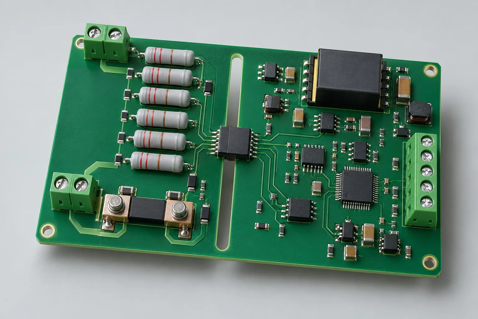
High-voltage isolated sensing design: separate example 400V DC divider-voltage and shunt-current front ends, listing isolators, power, error/drift, and insulation coordination separately. AMC1311-type voltage and AMC1300-type shunt channels differ. Compare totals only under identical environment/fault conditions.
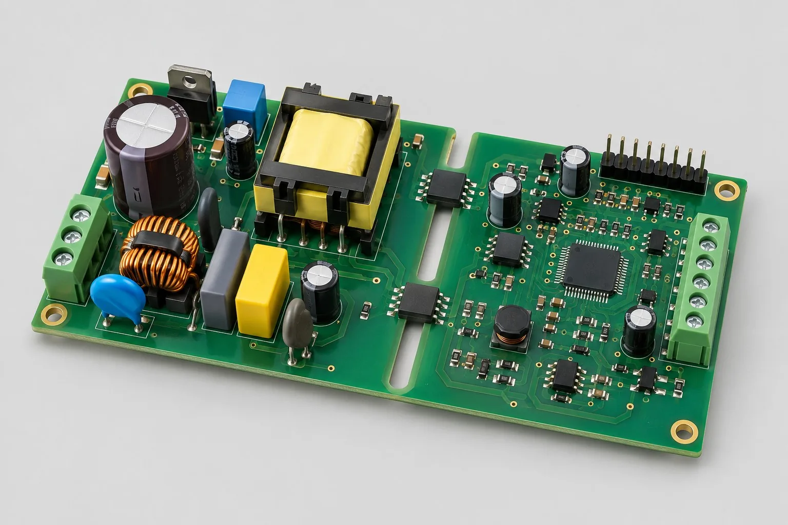
Isolated power controller design: list 24V auxiliary input, dual PWM candidates, isolated faults, and monitoring. Separate main topology, magnetics, and efficiency. Compare interface quotes by power-board pinouts/shutdown rather than inferring fees from 400V or product wattage.

Tell us the product use and which files are available. We can define the next engineering step even when the data package is not complete.