
Prototype Phase
Use fixed images and input data to check startup, memory, and camera/sensor interfaces, and trial-fit cooling components.
For edge-computing, vision-acquisition, and inference carrier boards, focus on BGA fanout, high-speed signals, power transients, thermal management, and firmware test paths.
Request AI Board Assembly →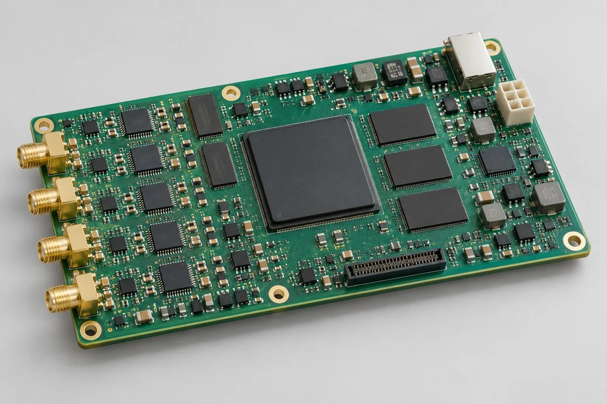
| Project Direction | PCB Manufacturing and Layout Focus | PCBA assembly and testing highlights |
|---|---|---|
| Edge computing carrier board | BGA/DDR fanout, stackup reference planes, power return paths, and high-speed connectors | Startup, memory, storage, network interfaces, and software revisions |
| Visual acquisition and interface board | Camera-interface impedance, connector positioning, clock noise, and power sequencing | Image input, link stability, frame data, and fault recovery |
| Sensing fusion control board | ADC/IMU interfaces, power partitioning, and critical clocks | Multiple inputs, time synchronization, interface communication, and calibration programming |
| Review Items | What specific inputs are provided | How to confirm results |
|---|---|---|
| High-speed and power supply | Interface rates, stackup, impedance table, power consumption, and power sequencing | Coordinate fabricator impedance compensation and assembly thermal processes in advance |
| High-density assembly | Actual BGA/QFN part numbers, package drawings, pads, IC heights, and cooling components | Check printing, support, reflow, hidden-joint inspection, and rework conditions |
| Functional Verification | Image/model revisions, boot method, test load, and permitted temperatures | Run board-level cases with fixed software and input data; assess application-algorithm performance separately |
Use fixed images and input data to check startup, memory, and camera/sensor interfaces, and trial-fit cooling components.
Confirm BGA hidden-joint inspection, measured thermal processes, and test loads; freeze software/model revisions and temperature criteria.
Deliver against approved images and board-level cases, recording startup, interface, and thermal states; algorithm-performance tests use separately agreed system conditions.
For AI projects, in addition to Gerber, drill files, BOM, pick-and-place files/CPL, and assembly drawings, include operating environment, actual interfaces/loads, enclosure and harness drawings, target quantity, and the test limits above. If commissioning programming or calibration, add software revision, checksum, fixture wiring, and programming permissions.
System algorithm and model performance use separate datasets and criteria; board-level assembly tests report only agreed hardware and software operating conditions.
View specific fabrication products by board-level task, or arrange a joint PCB fabrication and assembly review with complete information.
Engineering reference | QFN and SON assembly: thermal pads, printing, and solder joint verification: QFN/SON pad, stencil, and measured thermal process methods; not company capabilities.
Engineering reference | Packaging PCB fabrication files: units, layer order, and engineering notes: methods for PCB fabrication, hole layer spans, and file semantics.

Tell us the product use and which files are available. We can define the next engineering step even when the data package is not complete.