Engineering reference design · prototype validation pending
Sensor probe PCB design: remote probe-to-controller interconnects
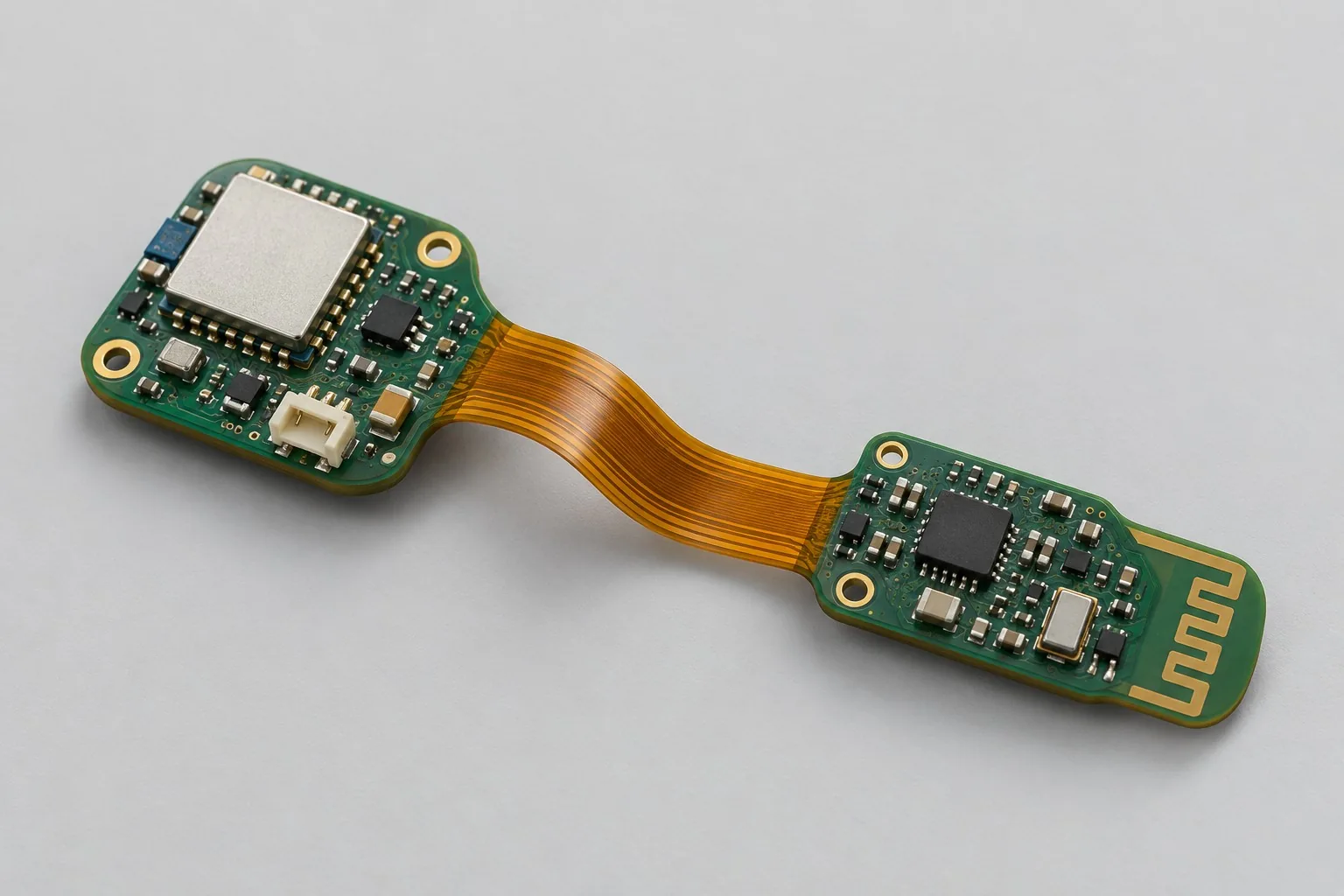
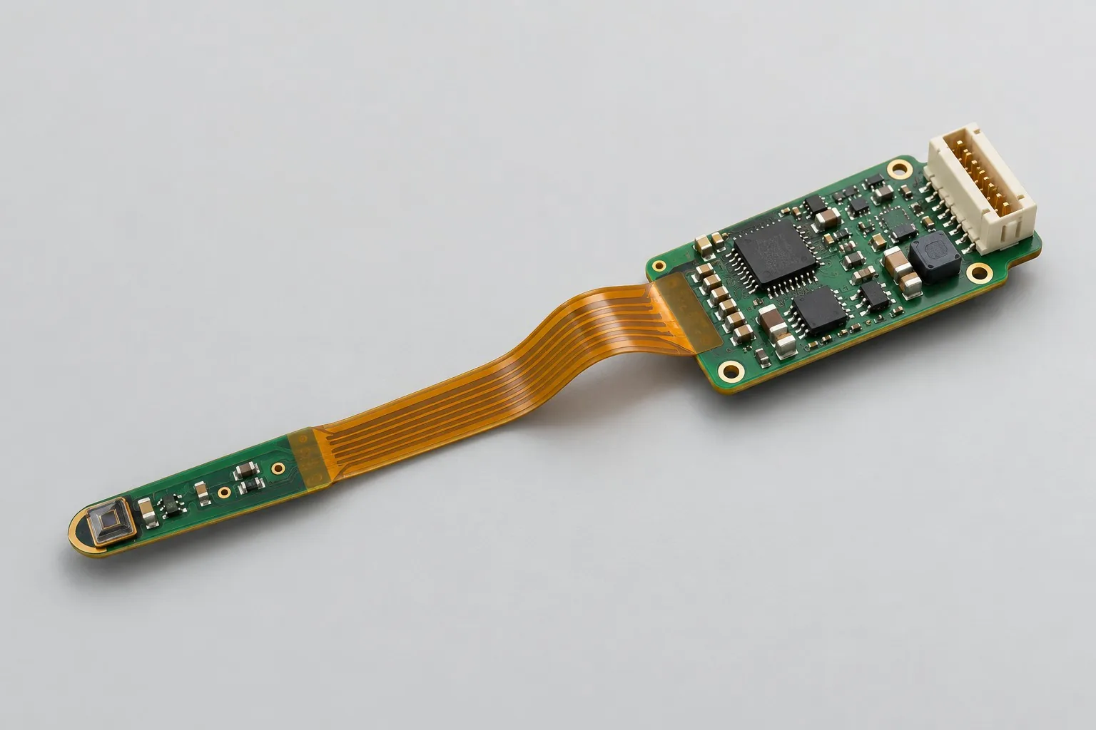
Foldable probe designs place sensors on narrow rigid sections away from controller heat. Flex sections carry signals/power and are folded once and secured during installation. Digital I²C and analog probes need different conditioning/tests. Record response time under actual clamping conditions.
Custom development reference design. The parameters below are requirement configurations and design targets; validate product performance through agreed prototype tests.
| Functional Partition | Design and verification scope |
|---|---|
| Probe Sensing End | Define digital temperature or analog probes and ranges, contact/air measurement, and narrow-slot installation. |
| Flexible Signal and Power Supply | Check bus capacitance, returns, and supply drop by flex length/rate; assess analog noise and input impedance separately. |
| Controller Rigid Area | The controller rigid section manages probe sampling and service interfaces; freeze software by sensor approach. |
| External Wiring Interface | Check external wiring locations/pinouts with fastening fixtures. Mechanical clamps, not flex sections, support probes. |
| Reference and Power | 5V-to-3.3V sensor domain; retain necessary probe-side power/ground continuity while reducing controller-to-probe heat conduction. |
| Forming / Cycle Recording | Compare continuity and bus/analog signals before/after folding, then response and thermal coupling. Continuous movement needs separate dynamic requirements. |
How much does rigid-flex sensor probe design cost, and how are quotes calculated?
Foldable probes require more than connecting two rigid boards. Probe type, flex geometry, mainboard heat, and installed response change circuit/mechanical verification; digital and analog inputs also differ. Check whether probe samples, mechanical adaptation, conditioning, and complete product calibration share the same quote scope.
Quotation terms depend on the approved files, quantity, material supply, tests and delivery requirements.
Prepare a structured RFQ or use the short inquiry form.
| Quotation Items | What services are included | What to Check When Comparing Quotes |
|---|---|---|
| Circuit and PCB Design | Probe rigid-flex interconnect and thermal impact | Reusable portions of existing designs and circuit/mechanical changes |
| Software and Validation | Folded structure and sensor response verification | Chip-interface debugging, assembled-probe response, and complete product calibration are separate scopes |
| Prototype Preparation | Bare PCB, BOM procurement, assembly, and agreed prototype quantity | Whether material/component revisions, prototype quantities, and test targets match |
| Subsequent Revision | Record new requirements separately from post-test corrections | How agreed changes, source files, and validation results are delivered |
How do rigid-flex and cabled sensor probes differ?
Rigid-flex integrates connections into the board; cables allow different distances and maintenance methods. Compare folded fastening, interface noise, and mainboard heat conduction rather than simply counting removed connectors.
How should digital and analog probes be selected?
Digital interfaces reduce some analog transmission work but remain sensitive to length and power. Analog probes need specific conditioning and noise budgets. Choose by probe model, location, and response requirements.
Do probe PCB quotes include complete product temperature calibration?
Chip-interface debugging, assembled-probe response, and complete product calibration are separate. Actual temperature accuracy requires verification including installation, mainboard heat, and calibration conditions.
Remote probe-to-controller interconnect reference configuration
| Configuration Field | Reference Configurations/Selections | Basis and Status |
|---|---|---|
| Finished Product Function | Main controller and remote sensor probe interconnect | Design Objective |
| Sensor Configuration | Digital temperature/I²C sensor or analog probe | Design Objective |
| Power Supply Objective | Controller-side 5V input → 3.3V sensor domain | Design Objective |
| Structural Form | Controller rigid section + narrow probe rigid section + flex section | Design Objective |
| Bend Type | Fold once during installation, static fixation | Design Objective |
| Stackup Candidate | Compare 4-layer rigid/2-layer flex or simpler construction | Design Objective |
| Signal Interface | I²C/analog signals; assess buffering by length | Design Objective |
| Thermal Isolation Target | Keep probes away from controller heat; reduce thermal conduction | Design Objective |
| Flexible Area Limit | No components, test points, or unnecessary vias | Design Objective |
| Fixing Method | Probe mechanical clamping, not relying on flexible area support | Design Objective |
| Maintenance Interface | SWD/test access in the controller rigid region | Design Objective |
| Validation outputs | Post-fold signals, response time, and thermal coupling | Design Objective |
Digital/analog probe and thermal coupling
Digital probes reduce analog-signal errors across flexible regions; long flexible sections still require bus-capacitance and waveform assessment.
Analog probes may support resistive/bridge sensing but require flex resistance, interference, and shielding review.
Changing static folds to continuous motion requires dynamic bending-life verification.
Design budget and trade-off examples
Check design targets with engineering calculations
At 16bit per sample and 1000 samples per second, raw data is 2kB/s. Interconnect constraints still depend on edge rates, interference, and analog signal conditions.
Conditions and Scope of Application:Low data rates do not eliminate return/shielding requirements. Define separate construction and tests for fixed forming and dynamic bending.
Replace examples with selected components and record margins; calculations support design choices, while prototype records support acceptance.
Remote probe-to-controller interconnect power and layout
- Reduce heat-conducting copper cross-section toward probes while preserving necessary returns and strength.
- Use smooth flex transitions; avoid overlapping stress concentrations at interconnect lengths, stiffener ends, and openings.
- Place probe pads and sensitive parts inside mechanically secured areas, away from bend edges.
Foldable probe R&D input
- Probe range, response time, and contact/air measurement method
- Fold location, clamp construction, flex length, and assembly sequence
- Ambient temperature, moisture/contamination, and maintenance disassembly counts
If circuit files exist, provide editable schematics, PCB, BOM, and current issues, and agree on review or revision scope. If only functions are defined, freeze this page's inputs before selection and circuit development. Agree separately on control-software and external-application responsibilities, interfaces, and acceptance.
Foldable probe phase delivery
| Stage | Engineering Work for This Proposal | Reviewable Deliverables |
|---|---|---|
| Requirements and Design Freeze | Freeze sensing approach, range/response, clamping, fold angle, and disassembly counts | Functional/interface requirements, mechanical revision, acceptance conditions, and open items |
| Schematic and Component Selection | Design sensor power, I²C/analog conditioning, flex interconnects, and controller servicing | Editable schematics, controlled BOM, footprint checks, and design calculations for these circuits |
| Layout and Routing | Implement probe rigid-section positioning, flex transitions/stiffeners, and low-conduction interconnects | PCB source files, actual stackup/hole/net constraints, DRC, and assembly-dimension checks |
| Simulation/Calculation | Assess bend boundaries, bus capacitance/analog noise, and controller thermal coupling | Design calculations/models, input conditions, margins, and items awaiting measurement |
| Prototype and Software | Build probes, integrate sampling, then fold/fasten with specified fixtures and sequence | Manufacturing package, probe prototypes, rigid-flex/clamp drawings, agreed acquisition firmware, sensor parameters, and calibration/response test notes |
| Testing and Version Closure | Compare pre-/post-fold signals; measure step response, continuity, and controller heating effects | Procedures, wiring, raw results, and decisions for the prototype revision; include issue/change and limitation lists |
Folded probe response and signal verification
- Pre-/post-fold bus waveforms/signal error comparisons
- Temperature step response coupled with main controller heat generation
- Electrical continuity and appearance after clamped installation
- Analog-input noise/power variation effects
Compare pre-/post-fold signals; measure step response, continuity, and controller heating. Reports identify equipment, conditions, revisions, and criteria, recording passed and uncovered items.
Foldable probe response and signal verification worksheet
The table turns remote probe interconnects into executable checks. Freeze samples, equipment, environment, and tolerances before execution; link results to this revision's raw records.
| Verification Object | Pre-Production Freeze | How to Test Prototypes in Practice | Delivery and Acceptance Records |
|---|---|---|---|
| Folding and Mounting | Static bend angle/radius, clamping areas, and assembly count | Fold/install in actual probe fixtures; measure continuity and appearance before/after | Retain dimensions and changes, identifying the baseline as nonrepetitive motion |
| Probe Response | Sensor type, measured environment, and response-time definition | Apply controlled temperature/signal steps and compare controller heating states | Deliver response curves, references, and thermal-coupling errors with fastening/contact methods |
| Flexible Area Transmission | Bus rate, flex length, and input impedance | Measure bus waveforms or analog noise before/after folding | Deliver rise-time/error-rate or noise data; length changes require renewed signal-margin checks |
Manufacturing and assembly coordination for this design
- Include stiffener thickness, coverlay, and probe-outline tolerances in fabrication drawings.
- Secure rigid sections before folding; fixtures maintain specified radii and directions.
Link design revisions to schematics, BOM, PCB, fabrication, and software documentation. When fabricators adjust stackup, materials, or holes, or Assembly parties propose substitutions, recheck critical electrical and test conditions together.
Common questions on purchasing and customization
How much does rigid-flex sensor probe design cost, and how are quotes calculated?
A project-specific quotation requires review of the available files, quantity, materials, requested tests, delivery destination, taxes, shipping, and trade terms. Complete development separately prices circuits, firmware, prototypes, and verification. Any formula on this page organizes cost inputs; it is not a quoted rate.View cost items, calculation conditions, and sources.
Can solder pads be placed in the probe folding area?
Define fastening/bending areas from rigid-flex construction, reviewing joints, stiffeners, and transitions for fabrication/assembly. Do not place them arbitrarily in moving areas.
How to compare response speed on probe prototypes?
Keep medium, installation, and temperature changes identical. Record probe/reference time curves and mainboard heating effects.
How should foldable probe budgets compare rigid-flex and cables?
At identical probe locations and heat sources, list rigid-flex stackup/static folding and cable connectors/buffering/maintenance. Keep response and thermal-coupling tests identical before comparing materials/assembly. Removing one connector alone does not identify the cheaper design.
Which sensing conditions must be frozen before probe layout-only work?
Choose digital temperature/I²C or analog probes, confirming length, power, fastening, and controller heat. Layout implements narrow probes, flex sections, and rigid-area test points. Review unresolved circuits, buffering, or thermal isolation first; folding does not replace temperature-sensing design.
Does an existing temperature driver still need complete product calibration software?
Drivers read chips; complete calibration also needs references, coefficient storage, and operating conditions. Raw-only requirements may omit calibration software. For actual accuracy, define thermal compensation and coefficient revisions rather than applying chip accuracy to assembled results.
How should probe deliverables support later length changes?
Retain flex lengths/bends, probe fastening, buffering, heat-source locations, and source files. Include sampling/calibration configurations, same-medium response curves, and mainboard heat effects, enabling electrical/thermal retest decisions after length changes.
Is changing a digital probe to analog merely a component substitution?
They need different front ends, references, and noise budgets, potentially changing flex signals/calibration. Assess retained controller mechanics separately. Redevelop interface software/response measurements; price circuits, routing, software, and verification separately rather than by probe price differences.
Can static-fold probes be reused in moving hinges?
This reference folds once during installation and then stays fixed. Hinges require redefined dynamic bending and loads. Some probe circuits may remain, but review flex materials, clamps, and cyclic continuity separately. Working static readings do not establish long-term motion reliability.
How should RFQ files be prepared for rigid-flex sensor probe design?
Initially describe functions, application, and files. Engineering quotes further confirm probe range/response/contact or air measurement; fold/clamp/flex length/assembly sequence; ambient temperature, moisture/contamination, and maintenance cycles. Supply editable schematics, PCB, and BOM for existing circuits, or fault-prototype revisions/reproduction records. List missing-data review tasks to prevent quotes based on different assumptions.
How should rigid-flex sensor probe prototype verification costs be compared by condition?
Fix prototype quantities, revisions, equipment, and criteria sources. Check separately: folding/installation, with frozen angles/radii/clamp areas/assembly counts and before/after continuity/appearance in actual fixtures; response, with fixed sensor/environment/time definitions, controlled temperature/signal steps, and controller heating comparisons; flex transmission, with fixed rates/lengths/input impedance and before/after waveforms or analog noise. Specify raw-data and issue-closure delivery. One power-on pass does not complete verification.
Compare related designs and plan the next step
Wearable positioning and sensing rigid-flex board design
Return rigid-flex PCB design selection · Select solution by device function · Discuss your design requirements
Documentation Basis and Boundaries
Engineering reference | Flexible and rigid-flex PCBs: bending, transition regions, and assembly: review rigid-flex construction, materials, and assembly routes; measure accuracy/response using selected sensors and actual installation.