Data Confidentiality
Discuss an NDA and define how drawings, BOM data, and production files may be used before sharing controlled information.
PROJECT-SPECIFIC REVIEW
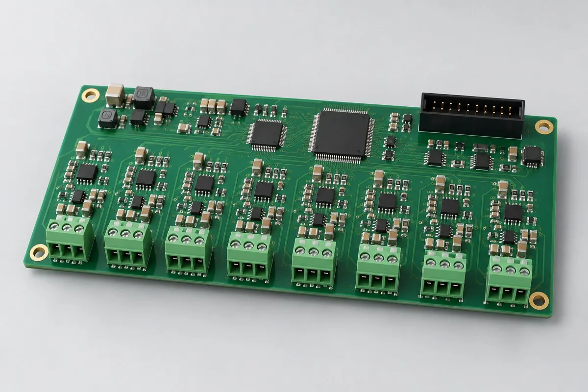
An SMT review connects land patterns, package types, paste, stencil design, placement, reflow, inspection, and handling. A machine model or nominal placement specification alone does not establish project capability.
Minimum package size, fine-pitch geometry, board handling, placement accuracy, reflow atmosphere, and inspection method remain subject to data review and the agreed acceptance standard.
The controlled quotation should identify the reviewed revision, included operations, exclusions, acceptance evidence, responsibilities, and release conditions.
| Work area | Inputs or responsibility | Expected output |
|---|---|---|
| Package | Approved ordering code and package drawing | Confirm footprint, polarity and handling restrictions |
| Panel | Rails, fiducials, underside components and support | Resolve support and handling conflicts |
| Placement | Units, origin, side and rotation convention | Check a known component independently |
| Process | Alloy, thermal restrictions and moisture handling | Agree conditions before material is exposed |
| Acceptance | Observable joints, hidden joints and functional requirements | Separate inspection evidence from behavior tests |
Use the assembly file checklist to prepare the discussion. Unknown inputs should be listed as open questions; they do not authorize substitutions, omitted tests or unrecorded design changes.
Start with the revision you intend to build and mark any missing record openly. The first enquiry can describe the product, quantity, board revision, supply model and the question to resolve; a complete engineering release packet follows when those facts are available.
| If this is missing | Send or confirm | Use this preparation guide | What remains open |
|---|---|---|---|
| Panel and support definition | Panel drawing, single-board outline, conveyor direction, rail and fiducial plan, both-side component projections and intended separation method. | Panel support and rail sign-off | Actual clamp and support clearance, board-position traceability and post-separation acceptance require a process trial. |
| Package-to-file agreement | Full manufacturer part number, package drawing revision, approved BOM, PCB copper/mask/paste outputs, stencil revision and centroid convention. | Package, footprint, stencil and placement cross-check | Unmatched library names, exposed-pad nets or rotation conventions must be resolved before assembly release. |
| Moisture-sensitive material history | Component labels, lot and package IDs, bag condition, opening and storage log, any split/return record and approved handling procedure. | Opened-reel and return history example | Missing exposure periods or unknown storage conditions require disposition; a reseal does not restore an unknown history. |
For a project review request, identify which records are ready and which decisions are still open. The quotation and agreed build plan should state the included assembly, inspection, test and material responsibilities. No example table on this page is a claim that a particular package, fixture or inspection method has been approved for your product.
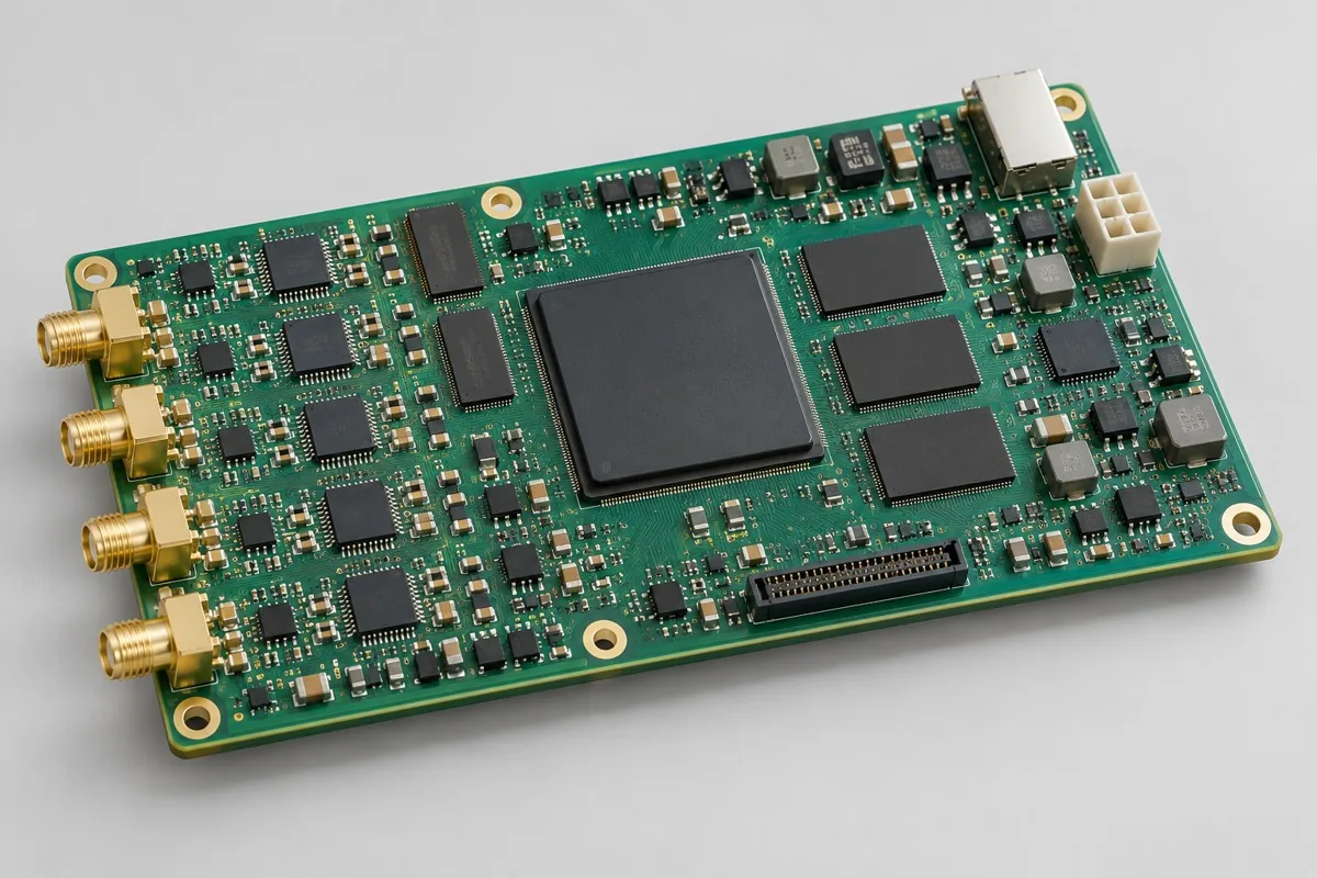 Engineering Reference Configuration
FPGA data acquisition boards support multichannel acquisition and data output. Review pricing against actual layer structures, FPGA/ADC sourcing, double-sided placement, bitstream programming, and acquisition tests; compare channel/interface configurations and define fixture and acquisition-software deliverables.
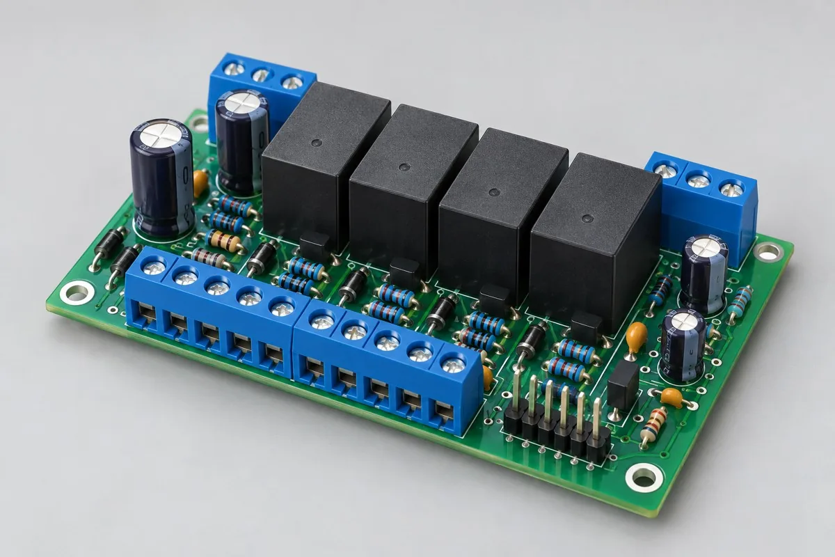 Engineering Reference Configuration
Relay control board through-hole assembly pricing depends on relays, terminals, control interfaces, and load conditions. Compare insertion, soldering, fastening, programming, and actuation-test scope; distinguish board-level checks from external-load verification, and check material supply and lot records.
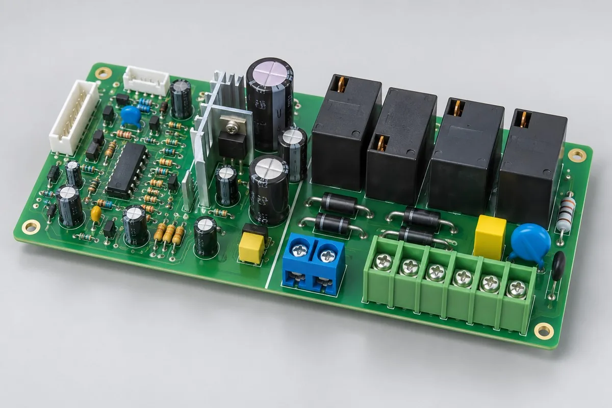 Engineering Reference Configuration
The air-conditioner control board through-hole assembly reference configuration covers compressor/fan relays and temperature inputs. Itemize SMT, lead forming, soldering, cleaning inspection, and functional testing; compare material supply, preparation, and per-batch assembly costs. Check sensor simulation, load timing, fault exits, and wiring test scope, and deliverables comprising control board + wiring/parameter table + functional results.
 Engineering Reference Configuration
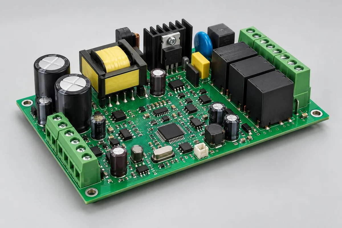
Industrial power supply board PCB assembly reference configurations cover power control, status acquisition, and fans/alarms. Separate SMT, grouped through-hole assembly (DIP), wave/post-soldering, cleaning, and testing; compare material supply, setup, and per-lot assembly costs. Check sampling, drivers, isolation regions, abnormal conditions, and thermal-state test scope, plus control board + through-hole/parameter revisions + test-record deliverables.
These company-document references and licensed process illustrations support engineering discussion. They do not prove current ownership, condition, availability, accuracy, capacity, or project suitability; routing and allocation are confirmed for each project.

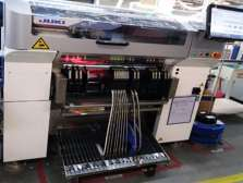

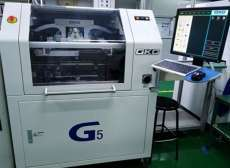
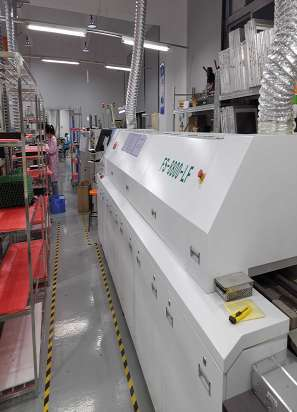


Line type, equipment allocation, staffing, reflow profile, inspection, and test scope are confirmed for each project after the manufacturing data has been reviewed.
Review PCB assembly requirements
| Process | Review input | Confirmation |
|---|---|---|
| SMT Assembly | Package mix, panel data, paste, and reflow constraints | Equipment route and schedule confirmed with the quotation |
| Through-Hole Assembly | Lead geometry, insertion method, and soldering constraints | Process route and inspection scope confirmed before release |
| Product Assembly | Mechanical drawings, fixtures, firmware, and test requirements | Assembly and test responsibilities recorded in the project scope |
Bare-board layer count, copper weight, and via structure do not replace checks for SMT packages, panelization, and soldering. Materials, process combinations, and production-site allocation are reviewed against the manufacturing data.
Review PCB fabrication parameters and combination limits · PCB and assembly co-review
Discuss an NDA and define how drawings, BOM data, and production files may be used before sharing controlled information.
Connect PCB design and DFMA with fabrication and assembly while keeping prototype and volume revisions aligned.
Agree incoming, in-process, and outgoing inspection requirements against the acceptance criteria for the project.
Define the engineering scope for communications, industrial-control, monitoring, and connected-product development.
Review quantity, supply model, processes, testing, and target date together before a manual quotation is issued.
Review the approved BOM, sourcing responsibility, and substitution authority before components are purchased.
The 2025 company profile lists NPM, JUKI, printing, reflow, and through-hole equipment; the applicable process window is verified for each project.
Set project milestones from data readiness, material readiness, and the confirmed production plan.
Review manufacturing and assembly requirements for medical, automotive, smart-home, industrial-control, AI-hardware, and IoT applications.

Tell us the product use and which files are available. We can define the next engineering step even when the data package is not complete.