
Industrial I/O gold-finger expansion module design
Define power, ground, and signal pinout for the board-edge interface first; distribute total contact current across enough parallel pins.
Design I/O expansion or communication cards for the baseboard pinout, slot, and power-off insertion/removal; check contact-current sharing, mechanical fit, interface transitions, and host compatibility. Start gold-finger boards with the host slot, pin definitions, and mechanical boundaries, delivering circuit functions and connection reliability together.
Configurations in this category support development requirements discussions. Actual components, structures, and performance are confirmed in the project revision; historical development directions and engineering references are identified separately.
This category covers industrial I/O plug-in cards and communication expansion cards. Costs are broken down by schematic, PCB layout, agreed software, and prototype validation scope; the main workload differences involve slot adaptation, gold-finger layout, protocols/drivers, and integrated debugging with the actual host. Layer count, board area, or channel count alone cannot determine development pricing; the usability of existing files and test conditions also affect the effort.
Quotation terms depend on the approved files, quantity, material supply, tests and delivery requirements.
Prepare a structured RFQ or use the short inquiry form.
| Quotation Items | What services are included | What to Check When Comparing Quotes |
|---|---|---|
| Existing circuit layout | Implement layout using approved schematics, footprints, and mechanical design | Whether schematic review, stackup/constraints, and fabrication files are included |
| From functional R&D | Slot adaptation, gold-finger layout, protocols/drivers, and integrated debugging with the actual host | Whether circuits, firmware, and validation targets are complete |
| Prototypes and revisions | Build prototypes from the frozen design, record test feedback, and release a controlled revision | Whether prototype quantity, component procurement, and change scope use the same basis |
Plug-in cards suit backplanes requiring module maintenance, but add pinout, contact, board-thickness, and mechanical-fit work. Fixed equipment can also use terminals or board-to-board connections; compare total costs by maintenance method.
Start selection with baseboard pinout, contact current, interfaces, and maintenance insertion/removal method, then review the parameters, cost boundaries, and validation conditions of the specific designs below.
| Review Questions | Why it impacts design | How to select and close |
|---|---|---|
| Mechanical Compatibility | Board thickness, bevel, plating, and contact regions directly affect mating. | Cross-check slot and PCB fabricator information, and draw contact-region keepouts and assembly dimensions. |
| Pins and timing | Power, ground, and signal arrangement affects return paths and insertion/removal. | Confirm host states, port protection, and power-on sequencing; hot-swap capability requires separate design and validation. |
| External I/O | Field terminals and host interfaces may have different ground references. | Check isolation, ESD, and shield connections, and define abnormal states. |
Slot part number, pin definitions, board thickness/bevel and positioning tolerances, insertion/removal method, supply, and hot-swap requirements.
| Current Stage | Customer-Supplied Materials | Design deliverables |
|---|---|---|
| Functional requirements only | Slot part number, pin definitions, board thickness/bevel and positioning tolerances, insertion/removal method, supply, and hot-swap requirements. | Functional/state requirements, approach comparison, mechanical design, and open items for I/O expansion and communication interfaces |
| Existing schematics or PCB | Editable circuit/PCB files, BOM, and mechanical design for products in this category; include slot part number, pin definitions, board thickness/bevel and positioning tolerances, insertion/removal method, supply, and hot-swap requirements. | Pin table, connector/board-edge dimensions, gold-finger fabrication requirements, and host compatibility records |
| Existing prototype pending revision | Fault reproduction conditions, raw logs/waveforms, test equipment, and original board revision | Troubleshoot faults related to I/O expansion and communication interfaces, and deliver revised files, an impact list, and regression records under the same operating conditions |
Define power, ground, and signal pinout for the board-edge interface first; distribute total contact current across enough parallel pins.
The SPI version facilitates embedded-controller connection; the USB version serves existing USB hosts. Switching between them requires more than changing the connector.
Pin table, connector/board-edge dimensions, gold-finger fabrication requirements, and host compatibility records. Link deliverables to the same requirements revision; the PCB fabricator confirms materials, stackup, holes, and fabrication conditions, while PCB assembly checks footprints, soldering, programming, and test points. Recheck this category's constraints after critical-component substitutions or mechanical changes.
Key validation in this category: mechanical mating, pin and interface compatibility, power/insertion/removal states, and agreed life conditions.
| Acceptance Stage | Conditions to be frozen | Report Records |
|---|---|---|
| Functionality and boundaries | Component/software revisions, supply/load, and interface or mechanical operating conditions | Test procedures, raw logs/waveforms, results, and abnormal states |
| Application-specific performance | Mechanical mating, pin and interface compatibility, power/insertion/removal states, and agreed life conditions | Instruments and calibration, environment, samples, criteria, and exclusions |
| Version Closure | Change list, permitted limitations, passed items, and open items | Fabrication and software packages, test reports, and issue-closure records |
Plug-in cards suit backplanes requiring module maintenance, but add pinout, contact, board-thickness, and mechanical-fit work.
First specify baseboard pinout, contact current, interfaces, and maintenance insertion/removal method.
Layout-only work can be discussed when usable schematics and component information exist. Starting from industrial I/O plug-in card or communication expansion card requirements requires selection and circuit design first. Itemize software, prototypes, and testing separately; do not treat layout fees as a complete development budget.
First itemize slot adaptation by baseboard pinout, board thickness, bevel, and contact current, then signal conditioning/controllers and software for I/O daughtercards or communication cards. Itemize actual-host, baseboard, and contact validation separately; hard-gold fabrication is only a manufacturing item and does not represent complete development costs for a maintainable plug-in card.
Freeze the mating slot, board thickness/bevel, keying, and contact region first, and confirm contact setbacks and keepouts. Layout implements mechanical and electrical constraints; if baseboard power/pinout is unresolved, perform interface design first. Generic gold-finger dimensions cannot promise compatibility with the customer's host.
For I/O cards, list scanning, diagnostics, and default outputs; for communication cards, list host initialization, drivers, and external-port recovery. If the customer supplies baseboard or host software, define adaptation scope. A basic power-off insertion/removal version does not automatically include hot-swap detection and recovery software.
Retain slot part numbers, contact mapping, board thickness/plating, and bevel conditions, and link source files to baseboard/host revisions. Keep software and actual contact/link records at the same revision; reassess fabrication changes against connector documentation, rather than retaining only board-edge outline drawings.
Added pins may affect slots, board outline, contact current, and backplane pinout; first confirm compatibility with the original baseboard. Separately list interfaces on both boards, software mapping, and mechanical validation. Added copper-contact area alone cannot determine whether the daughtercard change is minor.
Power-off insertion/removal does not prove hot-swap capability. Recheck power sequencing, current limiting, signal defaults, and software recovery. Identify reusable field-function modules, and separately account for slot and system-level validation; hard-gold contacts do not imply powered replacement is allowed.
Initially describe the product task, application, and current files. A formal quotation should confirm slot part number, pin definitions, board thickness/bevel and positioning tolerances, insertion/removal method, supply, and hot-swap requirements. If source files exist, provide circuit/PCB/BOM and mechanical revisions together; if prototypes exist, include fault conditions. First identify frozen functions and structures, then compare circuit, layout, software, and validation work; unresolved items must not be assumed to share the same service scope.
Key validation in this category: mechanical mating, pin and interface compatibility, power/insertion/removal states, and agreed life conditions. For each RFQ item, specify the actual load/interface or structure, prototype quantity, measurement method, equipment, and permitted deviation; deliver raw results, anomalies, and revision closure separately. Circuit/PCB checks and complete-unit functional validation are different tasks; a quotation including only the former does not justify omitting the performance measurements specific to this category.
Select and place components using the manufacturer information in the specific design details, and record file revisions and applicable conditions with the project; the company's historical development directions do not mean the reference designs on this page have been delivered in volume.
Return to the electronics design technical section · PCB Manufacturing · PCB assembly · Submit R&D requirements. When requesting gold-finger PCB design, prepare functions, interfaces, board outline, and existing design information.
Send the product functions, interfaces, mechanical constraints, available files, and required development stage. Compare design capability scope and development support before defining deliverables.
Compare reference designs by function, interfaces, and mechanical constraints, including design tradeoffs and prototype-acceptance methods.
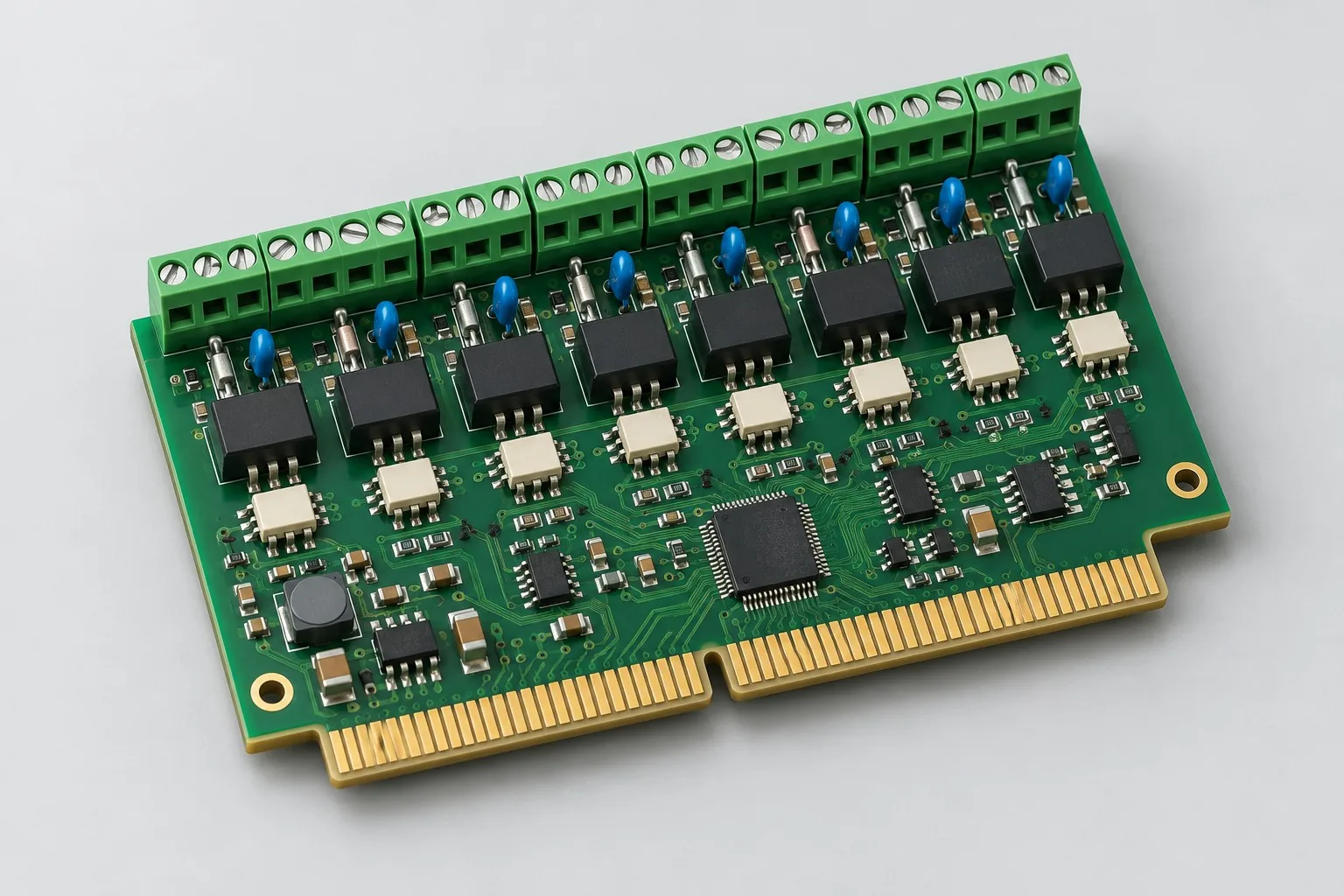
Industrial IO expansion design: itemize daughtercards with 8 24V inputs, 2 analog inputs, and 4 low-side outputs; backplanes cover power, slots, and SPI/RS485. Existing backplanes require adaptation and actual-board integration. Itemize new backplanes, fixtures, and mechanical locks separately; gold-finger fabrication costs are not complete plug-in-card development fees.
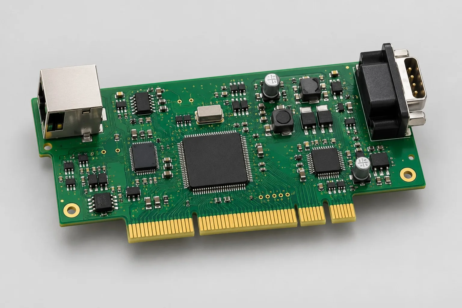
Communication interface card design: select host SPI or USB, then external 1-port 10/100M Ethernet or 2-port RS485, defining clear revision combinations. Itemize controllers/PHY, protection, host drivers, and actual-host integration separately; totals for different interfaces cannot identify the cheaper designer.

Tell us the product use and which files are available. We can define the next engineering step even when the data package is not complete.