Engineering reference design · prototype validation pending
Wearable PCB design: motion acquisition and Bluetooth
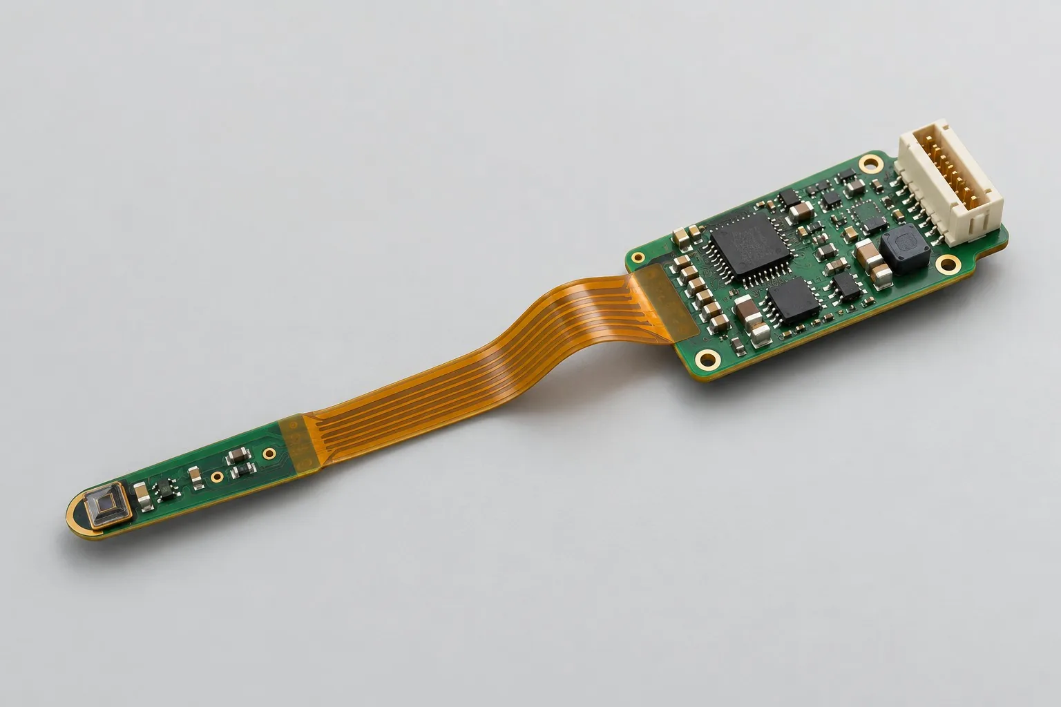
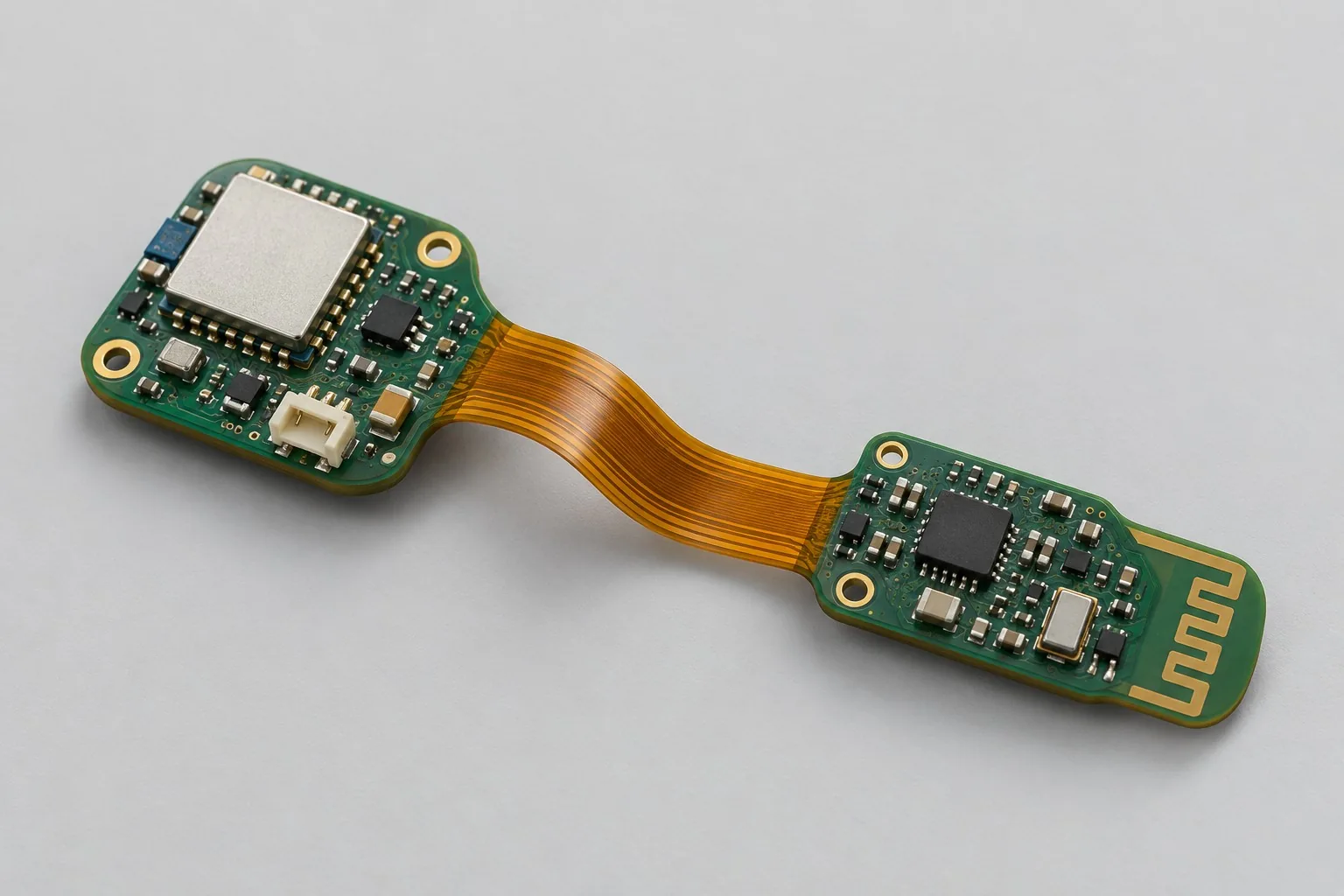
Wearable sensor rigid-flex designs place controllers, inertial sensors, and Bluetooth in rigid regions; flexible sections connect batteries/peripherals to fit curved wearable housings. Basic functions are motion acquisition/Bluetooth; GNSS is optional according to space/power budgets.
Custom development reference design. The following parameters are requirement configurations and design targets; validate functions and performance through agreed prototype tests.
| Functional Partition | Design and verification scope |
|---|---|
| Positioning / Sensor | Inertial sensors acquire motion through I²C and trigger wakeup. GNSS is an additional positioning option; Bluetooth does not replace satellite positioning. |
| Rigid Wireless Core Area | Keep Bluetooth controllers/antennas in rigid regions; define sampled data, configuration protocols, and worn wireless conditions. |
| Flexible Interconnect | Flexible sections carry power/signals; design returns/stress transitions for static mounting directions, radii, and assembly sequences. |
| Battery/peripheral rigid area | Place batteries, charging contacts, buttons, and test pads in rigid regions; flexible regions must not carry battery/component weight. |
| Low-Power Powering | Manage single-cell lithium power by domain; calculate acquisition/Bluetooth/optional GNSS task charge and flexible-region voltage drop. |
| Mechanical / Bend Verification | After enclosure installation, check flexible continuity, coverlay, and worn Bluetooth. Static forming records do not establish dynamic lifetime. |
How much does wearable rigid-flex design cost, and how is it quoted?
Costs depend on installation structures/functions. Static forming requires flexible-region, stiffener, and enclosure review; motion acquisition/Bluetooth add low-power and worn tests. GNSS changes antennas/budgets further. Itemize board structures, firmware, actual-enclosure verification, and samples.
Quotation terms depend on the approved files, quantity, material supply, tests and delivery requirements.
Prepare a structured RFQ or use the short inquiry form.
| Quotation Items | What services are included | What to Check When Comparing Quotes |
|---|---|---|
| Circuit and PCB Design | Rigid-flex structures, static forming, and low-power acquisition | Reusable portions of existing designs and circuit/mechanical changes |
| Software and Validation | Wearable and Wireless System Verification | Itemize basic motion acquisition/Bluetooth, added GNSS, system antennas, and battery tests separately |
| Prototype Preparation | Bare PCB, BOM procurement, assembly, and agreed prototype quantity | Whether material/component revisions, prototype quantities, and test targets match |
| Subsequent Revision | Record new requirements separately from post-test corrections | How agreed changes, source files, and validation results are delivered |
How should wearable rigid-flex boards and rigid boards with cables be selected?
Rigid-flex can reduce space/connections but adds structural/forming constraints. Rigid boards with cables simplify module replacement. Compare enclosures, fastening, and signals, beyond board-area pricing.
Do wearable boards require dynamic bending or static installation?
One-time forming followed by fixation differs from repeated in-use flexing. Define bend locations, radii, and cycles first; current static references are not dynamic-life designs.
Do wearable development fees include GNSS and battery-life verification?
Itemize basic motion acquisition/Bluetooth, GNSS additions, system antennas, and battery tests separately. Check space and task charge while selecting functions instead of maximizing functions before shrinking batteries.
Reference configuration for wearable motion acquisition and Bluetooth
| Configuration Field | Reference Configurations/Selections | Basis and Status |
|---|---|---|
| Reference application | Wearable motion sensing and Bluetooth with optional GNSS | Illustrative configuration; prototype validation required |
| Reference Function | Motion acquisition, Bluetooth, and optional positioning modules | Design Objective |
| Power Supply Configuration | Single lithium battery plus charging protection | Design Objective |
| Rigid Area Structure | Controller rigid region plus sensor/interconnect rigid region | Design Objective |
| Flexible Connection | 2-layer flexible-section candidate; static installation bends | Design Objective |
| Layer Candidate | Rigid 4-layer/flexible 2-layer construction; joint stackup review | Design Objective |
| Sensor Interface | I²C inertial sensor plus interrupt wake-up | Design Objective |
| Wireless Configuration | Bluetooth module; assess GNSS separately by available volume | Design Objective |
| Bend Boundary | Radii/angles defined by actual stackups and assembly processes | Design Objective |
| Interface Arrangement | Charging contacts, buttons, and test points in rigid regions | Design Objective |
| Package Constraint | Components avoid bend zones and rigid-flex boundaries | Design Objective |
| Validation outputs | Assembly bends, electrical continuity, and system power consumption | Design Objective |
Static shaping and GNSS option
Flexible sections eliminate cables/connectors and accommodate shape. If a loose ribbon cable alone meets requirements, compare cost and maintainability first.
This page defines static installation bending; repeated dynamic folding requires separate fatigue requirements.
Wearable sensor data supports motion logging; this design makes no medical health claims.
Design budget and trade-off examples
Check design targets with engineering calculations
Assuming flexible-interconnect supply-loop resistance 0.4Ω and pulse current 200mA, voltage drop is 80mV; add connector and dynamic supply-response effects separately.
Conditions and Scope of Application:This cannot determine bend lifetime/radius; review static/dynamic structures, materials, and motion conditions separately.
Replace examples with selected components and record margins; calculations support design choices, while prototype records support acceptance.
Power and layout for wearable motion acquisition and Bluetooth
- Route flexible traces smoothly away from edges; provide transitions/mechanical stress relief near rigid-flex boundaries.
- Avoid vias, pads, and local heavy copper in bend sections; open coverlay only where soldering is required.
- Prefer rigid-region wireless antennas; include nearby battery/body effects in system tests.
Wearable rigid-flex PCB R&D input
- Curved enclosure three-dimensional models, bend angles, and installation sequence
- Battery dimensions, charging methods, and wearing positions
- Sensor/wireless functions, target temperatures, and protective structures
If circuit files exist, provide editable schematics, PCB, BOM, and current issues, and agree on review or revision scope. If only functions are defined, freeze this page's inputs before selection and circuit development. Agree separately on control-software and external-application responsibilities, interfaces, and acceptance.
Wearable rigid-flex PCB phase delivery
| Stage | Engineering Work for This Proposal | Reviewable Deliverables |
|---|---|---|
| Requirements and Design Freeze | Freeze motion acquisition/Bluetooth, optional GNSS, wearing positions, curved structures, and assembly bends | Functional/interface requirements, mechanical revision, acceptance conditions, and open items |
| Schematic and Component Selection | Design inertial sensing, Bluetooth controllers, charging protection, and rigid-flex pinouts | Editable schematics, controlled BOM, footprint checks, and design calculations for these circuits |
| Layout and Routing | Define rigid/flexible regions, no-bend/keep-out areas, antenna clearances, and battery-mounting constraints | PCB source files, actual stackup/hole/net constraints, DRC, and assembly-dimension checks |
| Simulation/Calculation | Review bend geometry, flexible voltage drops, task charge, and body/enclosure wireless effects | Design calculations/models, input conditions, margins, and items awaiting measurement |
| Prototype and Software | Build rigid-flex prototypes; integrate motion acquisition, Bluetooth, and optional GNSS, then install enclosures in sequence | Manufacturing package, rigid-flex region/assembly drawings, wearable prototypes, agreed acquisition/Bluetooth firmware, option lists, and charging-recovery instructions |
| Testing and Version Closure | Verify static-forming continuity, worn data links, charging temperature rise, and approved environmental scenarios | Procedures, wiring, raw results, and decisions for the prototype revision; include issue/change and limitation lists |
Wearable acquisition and static bend verification
- Electrical continuity after initial assembly and disassembly/reassembly
- Conductor/coverlay appearance under specified static bends
- Bluetooth/motion data while worn; separate positioning tests for optional GNSS
- Charging temperature rise and sweat/condensation environmental test plans
Verify static-forming continuity, worn data links, charging temperature rise, and approved environmental scenarios. Reports specify equipment, conditions, revisions, and criteria, recording passed and uncovered items.
Worn acquisition and static-bend verification worksheet
The table converts wearable motion acquisition/Bluetooth into executable checks. Freeze samples, equipment, environments, and allowable deviations before execution; link results to this revision's raw records.
| Verification Object | Pre-Production Freeze | How to Test Prototypes in Practice | Delivery and Acceptance Records |
|---|---|---|---|
| Static Bend | Enclosures, bend radii, assembly sequences, and disassembly requirements | Assemble frozen structures, then inspect flexible-region appearance/electrical continuity | Retain bend locations/radii and sample records; static assembly results do not establish dynamic lifetime |
| Wearable Wireless | Wearing positions, antennas, batteries, and body-proximity scenarios | Compare desktop/worn Bluetooth and motion data; record positioning separately for optional GNSS versions | Deliver test orientations, enclosure revisions, and signal differences, tracking structural-change effects |
| Environment and Charging | Sweat/condensation conditions, coating boundaries, and charging thermal targets | Perform approved environmental prescreens, then test charging/sensing | Deliver treatment conditions, leakage/appearance, and temperature rise; environmental ratings require corresponding tests |
Manufacturing and assembly coordination for this design
- Review stackups, coverlay, stiffeners, and boundary tolerances jointly with rigid-flex fabricators.
- Assembly fixtures constrain bend locations so components/joints do not carry operator-applied bending loads.
Link design revisions to schematics, BOM, PCB, fabrication, and software documentation. When fabricators adjust stackup, materials, or holes, or Assembly parties propose substitutions, recheck critical electrical and test conditions together.
Common questions on purchasing and customization
How much does wearable rigid-flex design cost, and how is it quoted?
A project-specific quotation requires review of the available files, quantity, materials, requested tests, delivery destination, taxes, shipping, and trade terms. Complete development separately prices circuits, firmware, prototypes, and verification. Any formula on this page organizes cost inputs; it is not a quoted rate.View cost items, calculation conditions, and sources.
Why do wearable prototypes need actual enclosures?
Assembly positions affect antennas, batteries, and flexible regions; actual enclosures help check worn orientation, fastening, and communication.
How to inspect motion acquisition on wearable boards?
Fix sensor orientation/worn installation; record stationary/motion data, sample timing, and wireless uploads instead of merely checking readable sensor registers.
How should wearable rigid-flex budgets separate base and extension scope?
Bundle basic motion acquisition, Bluetooth, and single-cell lithium power; separately list optional GNSS, charging structures, and system battery-life tests. Rigid 4-layer/flexible 2-layer construction awaits joint review. Confirm static forming/worn-position verification first; do not ambiguously bundle dynamic lifetime, positioning, and system tests into one rigid-flex fee.
What mechanical inputs are needed for rigid-flex Layout-only work?
Provide controller/sensor rigid-region positions, flexible routes, mounting angles, fastening, and actual stackups, defining component/via bend keep-outs. Layout implements board geometry/returns. Undefined wearable structures, Bluetooth antennas, and battery space need electromechanical review first; free-bending photos do not replace structural conditions.
What motion-acquisition development remains when Bluetooth software exists?
Confirm inertial-sensor orientation, sample rates, interrupt wakeup, and frames; handle worn orientation/disconnection buffering. Existing Bluetooth connection code may be reused, but reading/wakeup timing and task charge still require measurement. Phone connectivity alone is not complete acquisition.
What assembly constraints should wearable rigid-flex sources include?
Agree rigid/flexible stackups, bend keep-outs, mounting points, charging contacts, and antenna clearance; link PCB/mechanical revisions. Software includes sensor coordinates, wakeup, and Bluetooth configuration. Reports include actual-enclosure continuity/power data. Manufacturing Gerber cannot replace editable rigid-flex structures.
What work must be requoted when static boards change to repeated motion?
Redefine radii, cycles, motion paths, and allowable resistance changes, then review flexible materials, copper, and transition reinforcement. Static installation does not establish dynamic lifetime. Itemize structural development, samples, and cycle verification separately instead of merely changing acceptance cycle counts.
Who prepares wearable rigid-flex prototype enclosures and forming tools?
Provide actual enclosures/mounting drawings for controller/sensor rigid regions and static flexible sections. Separate customer samples, forming-resource fabrication, and post-assembly electrical/power verification in quotations. Record structural revisions, positions, and charging contacts. Existing Bluetooth software/PCB sources do not replace assembly resources; tool reuse still requires new-stackup/mounting-point checks.
How should quotation documentation be prepared for wearable rigid-flex design?
Initially describe functions, applications, and files. Engineering quotations further confirm curved-enclosure three-dimensional models, bend angles, installation sequence, battery dimensions, charging, wearing positions, sensor/wireless functions, temperatures, and protective structures. Provide editable schematics, PCB files, and BOMs for existing designs, or revisions/reproduction records for faulty prototypes. List gaps as review tasks to prevent differing assumptions.
How should wearable rigid-flex prototype verification costs be compared by operating condition?
Fix prototype quantities, revisions, equipment, and criteria sources. Separately review static bends: freeze enclosures, radii, assembly/disassembly requirements; assemble and check appearance/continuity. Worn wireless: freeze positions, antennas, batteries, and body proximity; compare desktop/worn Bluetooth/motion data, recording optional GNSS separately. Environment/charging: freeze sweat/condensation, coating boundaries, and thermal targets; prescreen under approved plans, then test charging/sensing. Specify raw-data and issue-closure deliverables; one successful power-up is not complete verification.
Compare related designs and plan the next step
Folding sensor probe rigid-flex design
Return rigid-flex PCB design selection · Select solution by device function · Discuss your design requirements
Documentation Basis and Boundaries
Engineering reference | Flexible and rigid-flex PCBs: bending, transition regions, and assembly: Check rigid-flex transitions, bends, and manufacturing structures; this does not establish Bluetooth/GNSS functions, worn accuracy, or battery life.