PCB ASSEMBLY · ELECTRONIC ASSEMBLY
Smart Bed Multi-Interface PCBA Engineering Example
Engineering Application Example
Illustrative smart-bed control PCBA example covering wired controls, actuator interfaces, connector identification and position-feedback records.
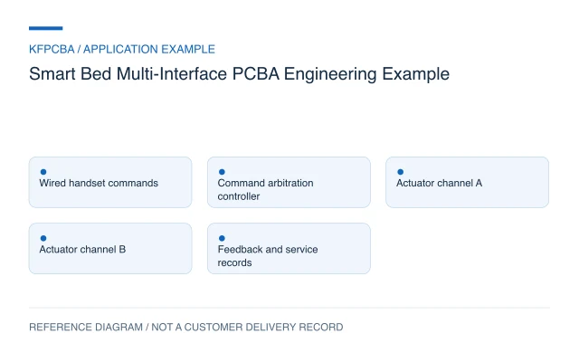
Illustrative engineering application example, not a KFPCBA customer delivery or measured production record. The configuration, calculations and record examples below are hypothetical planning inputs requiring project-specific review.
Requirements for a multi-interface bed controller
This example considers a household adjustable-bed controller connecting a wired handset, two separately identified actuator channels and service access. It does not describe a medical-bed product, a completed motion-control design or a tested bed mechanism. Begin with an interface schedule giving every connector's function, pinout, mating part, cable length and mounting location. Identify which actuator changes which bed section, and define how the user requests, stops and reverses movement.
The product owner must specify command priority, simultaneous-motion rules, power-restoration behavior and responses to missing controls or feedback. A handset button, an actuator limit input and a position pulse are different information sources. Preserve their identity in the firmware and test records. Wireless operation, massage functions, memory presets and accessories require explicit requirements rather than assumptions based on the term smart bed.
Design constraints and the actuator-interface decision
Choose between controlling a complete external actuator module and driving a specified motor through an on-board power stage. These alternatives have different BOM, thermal and verification responsibilities. The TI DRV8876 documentation describes an H-bridge driver with integrated current sensing and regulation for brushed-motor applications. It is a component example, not evidence that this device suits an unidentified bed actuator.
If an on-board driver is considered, obtain motor current profiles, supply behavior, feedback format and the actuator's internal limit arrangement before selection. Current sensing does not by itself establish obstruction detection or a validated protective function. Where an external actuator controller is used, define its request and status protocol instead of assuming the main board directly switches motor current.
Two physically similar connectors can still serve opposite bed sections or incompatible accessories. Prefer unambiguous keying when the design allows it, and always retain connector IDs and harness labels. Mounting and cable routing must account for the moving mechanism without treating the board assembly drawing as a complete mechanical assessment.
Reference configuration and a position-count calculation
| Block | Reference responsibility | Required definition |
|---|---|---|
| Handset input | Interpret user commands and release events | Button behavior and command priority |
| Main controller | Arbitrate actuator requests and record faults | State machine and restart policy |
| Actuator interfaces | Issue commands and read specified feedback | Drive ownership, limits and pinout |
| Service connection | Program firmware and retrieve records | Access, configuration and recovery |
Hypothetical calculation: assume an actuator-feedback system has a verified conversion of 40 counted pulses per millimetre. A movement producing 480 pulses corresponds to 480 ÷ 40 = 12 mm of inferred travel. The conversion is an assumption for this example, not a generic actuator characteristic. Missed pulses, gearing, backlash and power interruption can affect inferred position; counting alone does not establish absolute position.
Assembly and procurement choices
Control the handset, actuator connector and harness part numbers with the board BOM. If the scope includes finished-cable mating, specify that operation separately from cable cutting and crimping. Record connector opening directions, latch access, cable exits and board-fastener positions. A connector that solders correctly can still be inaccessible after installation.
When a motor driver or current-sensing part changes, review the electrical configuration and firmware scaling as well as the footprint. For mixed SMT and through-hole assembly, identify large connectors and components that obstruct insertion or inspection. A DFMA review should use the board drawing and representative mounting geometry, including the intended mating plugs.
Verification matrix for interfaces and command behavior
| Scenario | Check | Record |
|---|---|---|
| Individual handset command and release | Verify the selected channel and commanded state | Button ID, channel mapping and event timestamps |
| Competing requests | Exercise the specified arbitration sequence | Input sequence and resulting controller state |
| Known feedback pulse train | Verify count, direction interpretation and scaling | Simulator setting, raw count and calculated travel |
| Power interruption or disconnected control | Observe the defined restart and missing-input policy | Reset cause, retained data and output requests |
A simulator can check interface mapping and logic. Representative actuator testing adds actual electrical behavior; complete-bed evaluation adds mechanism, loading and user interaction. The product-test scope must identify these as separate activities with supplied fixtures and agreed criteria. Board-level pulse counting does not establish synchronized motion, load capacity or entrapment protection.
Handoff documents and a channel record
Provide PCB files, BOM, placement and assembly data, connector schedule, harness and mounting drawings, actuator documentation, firmware hash and test procedure. State where presets and position estimates are stored, whether they survive power loss and how replacement boards are configured. Include a versioned command dictionary for the handset or external actuator module.
A proposed record template is: board serial; firmware hash; handset variant; actuator channel; connector ID; command sequence; feedback count; inferred travel; reset event; disposition. Keep these fields separate so a swapped harness is not misdiagnosed as a scaling error. Submit the controlled package through the engineering RFQ, listing board assembly, harness operations, actuator supply and complete-bed tests independently.
Three planning scenarios
The head-section command moves the foot section. What should be reviewed first?
Compare connector IDs, harness labels, handset mapping and the installed firmware configuration. Trace the command to the physical channel before changing motor direction or position coefficients.
Can a stored pulse count restore position after power loss?
Only within a validated position strategy. Review what motion can occur while counting is unavailable, how data is committed and how the mechanism establishes a reference. A saved number alone is insufficient evidence.
A new actuator has the same plug. Can it replace the original?
Review pinout, motor demand, feedback, internal limits, travel and mounting geometry. The replacement also needs the relevant controller and mechanism evaluation; a mating connector does not establish compatibility.
Source material and applicable scope
- Texas Instruments DRV8876 product documentation. Checked 11 November 2026. The public page lists H-bridge operation, current sensing and regulation; these component features do not establish actuator suitability, synchronized bed movement or a protective function. Applies to an optional brushed-motor H-bridge architecture with integrated current sensing and regulation. This source does not document a KFPCBA build, production result, approved BOM or complete-product compliance.