PCB ASSEMBLY · ELECTRONIC ASSEMBLY
Brushless Motor Control PCBA Engineering Example
Engineering Application Example
Illustrative brushless-motor control PCBA example covering the gate driver, external power stage, current sensing and mixed-technology assembly.
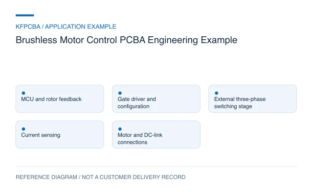
Illustrative engineering application example, not a KFPCBA customer delivery or measured production record. The configuration, calculations and record examples below are hypothetical planning inputs requiring project-specific review.
Requirements for a brushless motor-control board
This example considers a three-phase brushless motor controller with a separate MCU, gate driver, external power switches, current sensing and motor connections. It is an architecture for discussing assembly and verification, not a released motor drive. The design owner must provide the supply profile, motor electrical data, startup load, speed range, direction requirements, feedback method and fault behavior. Power capability cannot be derived from the number of transistors or the size of an electrolytic capacitor.
Choose whether rotor information comes from Hall signals, an encoder or a defined sensorless algorithm. That choice affects connectors, signal conditioning and firmware, and it changes how a prototype can be tested. Identify whether braking or deceleration returns energy to the supply. The power source and system mechanics must be included in that review.
Design constraints and the gate-driver decision
The TI DRV8323 documentation describes a three-half-bridge gate driver for external N-channel MOSFETs, with current-shunt amplifier and interface options within the family. This supports distinguishing gate-control functions from the external switching stage. It does not establish the assembled board's continuous current, motor compatibility or thermal performance.
Freeze the exact driver variant and configuration interface. Hardware-strapped and serially configured options require different assembly and firmware controls. Review gate loops, current-sense routing, decoupling and return paths against the selected datasheet. An alternate MOSFET with a similar headline resistance can have different gate charge and switching behavior, so substitution requires a power-stage review rather than a package-only comparison.
Reference configuration and a conduction-loss calculation
| Block | Reference choice | Release question |
|---|---|---|
| Control | MCU with defined feedback input | Commutation and current-sampling method |
| Gate drive | Three half-bridge driver | Exact interface and settings |
| Power stage | External switches and DC-link capacitors | Switching, thermal and supply-energy review |
| Connections | Phase, supply and feedback interfaces | Pin order, retention and test access |
Hypothetical calculation: consider one conducting path whose two switches together have an assumed resistance of 0.020 Ω at the evaluated condition. At 4 A, its instantaneous conduction loss is I²R = 4² × 0.020 = 0.32 W. This is not total inverter dissipation. The actual conduction sequence, temperature-dependent resistance, switching loss, gate-drive loss and copper loss must be added before assessing a thermal design.
Assembly and procurement choices
Control the power-switch part number, shunt value, gate components and capacitor series in the BOM. Specify capacitor polarity, diameter, height, lead spacing and any approved lead forming. A mechanically taller substitute can conflict with the enclosure or cooling hardware even when the capacitance matches. Mark unpopulated option positions and configuration resistors explicitly.
Plan SMT and through-hole operations around access to the power area. Heatsink hardware, insulators where specified, fasteners and phase connectors require drawing references and assembly ownership. Do not infer a soldering or thermal-interface process from an image. A DFMA review should identify insertion access, mechanical stress, rework access and inspection needs for the actual packages.
Verification matrix from unpowered board to motor operation
| Stage | Check | Evidence |
|---|---|---|
| Unpowered assembly | Polarity, configuration, connectivity and fastening | Revision, inspected locations and disposition |
| Controller and driver access | Read configuration or verify hardware settings | Firmware hash and configuration snapshot |
| Controlled switching evaluation | Observe gate behavior using the approved setup | Probe method, waveform and operating condition |
| Defined motor/load run | Check startup, feedback, fault response and temperatures | Motor ID, load profile, duration and measured channels |
The staged plan is a discussion framework, not permission to energize an unreviewed power stage. A qualified test owner must define the setup, sequence and limits. Motor-driver PCBA prototyping should distinguish assembly inspection from switching analysis and from loaded motor characterization. Each produces different evidence and requires different support.
Handoff documents and a configuration record
Provide schematic and layout sources, manufacturing files, BOM, placement data, assembly and mechanical drawings, motor datasheet, firmware hash, driver settings and test procedure. Include a list of settings that must be programmed per unit and those fixed by hardware. If cooling hardware is external, supply its interface and ownership.
A hypothetical record template is: board serial; power-stage BOM revision; driver variant; firmware hash; configuration checksum; motor ID; supply setup; load point; waveform file; thermal observation; fault code; disposition. No efficiency or temperature result is assumed. Submit files through a project inquiry, naming component supply, programming, fixture development and motor testing separately.
Three planning scenarios
The motor turns at no load. Does that establish the drive rating?
No. The result only addresses that setup. Review the intended motor, supply, load cycle, cooling and switching conditions, then define the evidence needed at representative operating points.
A capacitor of equal capacitance is available sooner. Can procurement substitute it?
Review its electrical series characteristics, temperature conditions, lifetime basis, dimensions and mounting requirements against the design. Equal capacitance and pin spacing alone do not establish equivalence.
A driver fault appears only after a firmware change. Should assembly be reworked first?
Compare configuration, timing and fault registers with the prior revision, retaining waveforms from the approved setup. Rework should follow evidence of an assembly issue, not the existence of a fault flag alone.
Source material and applicable scope
- Texas Instruments DRV8323 product documentation. Checked 11 November 2026. The public page identifies external N-channel MOSFET drive, current-shunt amplifier options and SPI or hardware interfaces; board ratings and motor results remain design-specific. Applies to the distinction between a three-half-bridge gate driver, external MOSFETs and configurable sensing/interface functions. This source does not document a KFPCBA build, production result, approved BOM or complete-product compliance.