PCB ASSEMBLY · ELECTRONIC ASSEMBLY
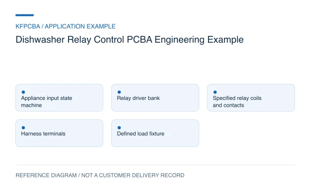
Dishwasher Relay Control PCBA Engineering Example
Engineering Application Example
Illustrative dishwasher control PCBA example covering relay selection inputs, terminal mapping, control-supply demand and verification planning.
Illustrative engineering application example, not a KFPCBA customer delivery or measured production record. The configuration, calculations and record examples below are hypothetical planning inputs requiring project-specific review.
Requirements for a relay-based appliance controller
This example considers a dishwasher control board with a logic section, relay drivers, relays and external harness terminals. The objective is to organize the information needed for assembly and board verification. It is not a released appliance electrical design. List every switched load by its actual characteristics and operating sequence, distinguishing a pump, valve, heater request and other equipment functions. A shared word such as output does not make their switching requirements equivalent.
Provide the intended de-energized state, permitted simultaneous operations and required response to missing inputs. Door sensing, water-level information and temperature information may affect an appliance state machine, but their presence on a connector list does not establish a protective function. The product owner must define the complete control and appliance-validation requirements before a manufacturing plan can be accepted.
Design constraints and the relay-selection decision
The OMRON general-purpose relay guide distinguishes mechanical and electrical durability and discusses the effect of load conditions on contacts. This supports reviewing the actual load and switching duty instead of choosing a relay only by package or one headline current value. It does not approve a relay for a particular dishwasher.
Control the coil type and voltage, pin arrangement, contact form and applicable load data in the BOM. Review the selected relay's suppression and driver circuit with its own documentation. Contact-load suitability, installation environment, electrical separation and applicable appliance requirements remain design-review topics. No insulation distances, voltage-withstand figures or safety limits are specified by this example.
Terminal blocks and harness plugs must match the electrical schedule and mechanical drawing. Define connector views carefully: a mating-face view and a board-side view can reverse an apparent pin order. Include terminal position numbers and a single reference orientation so purchasing, assembly and test fixtures use the same mapping.
Reference configuration and a coil-budget calculation
| Block | Reference task | Release input |
|---|---|---|
| Logic and inputs | Evaluate the defined appliance state machine | Input definitions and fault policy |
| Relay drivers | Energize the selected coils | Coil and driver data |
| Relay contacts | Switch individually specified loads | Load profile and switching duty |
| External terminals | Connect the approved harness | Pin table, plug and mounting information |
Hypothetical calculation: assume four relay coils each require 40 mA from a 12 V control supply and all four may be energized together. Their nominal combined current is 4 × 40 = 160 mA. Coil demand is 12 × 0.160 = 1.92 W. Logic, indicators, driver losses and supply margin are additional. This budget says nothing about the loads switched by the contacts and cannot establish a relay contact rating.
Assembly and procurement choices
Separate relay variants that share a housing but differ in coil or contact configuration. Record the complete manufacturer part number, not a shortened series name. For terminal parts, control entry direction, pitch, locating features and mating hardware. Assembly drawings should show relay orientation, seating expectations and locations where bulky parts limit soldering or inspection access.
Plan SMT and through-hole operations from the actual component requirements. Any cleaning, coating or masking instruction must be compatible with the selected parts and defined process; coating does not by itself demonstrate moisture protection. Use DFMA review to identify component access and harness fit, then keep appliance-level environmental evaluation as a separately specified activity.
Verification matrix for logic, coils and mapping
| Condition | Check | Evidence to retain |
|---|---|---|
| Individual output request | Confirm the corresponding driver, coil and terminal mapping | Command ID, physical channel and fixture revision |
| Permitted simultaneous commands | Observe control-supply behavior with defined dummy loads | Coil population, supply measurement and timing |
| Input transition or missing input | Exercise the approved state-machine sequence | Input state, commanded outputs and recovery |
| Harness and enclosure fit | Mate the specified connectors in the fixture | Orientation, retention and access observations |
A relay click cannot verify the switched load's electrical behavior or contact life. Where required, representative load switching needs an approved fixture, operating sequence and acceptance criteria. A product-test scope should distinguish continuity or dummy-load checks from loaded switching, endurance, environmental and complete-appliance evaluations. No such test result is asserted here.
Handoff documents and an output record
Provide the BOM, PCB data, placement and assembly files, output/load schedule, harness drawing, state-machine definition, firmware hash and test procedure. Identify the revision of each load component used for validation. Specify whether relays and mating plugs are sourced with the board or supplied by the product owner.
A proposed record is: board serial; relay part number; hardware revision; firmware hash; command ID; coil channel; contact-terminal mapping; load-fixture ID; observed state; disposition. Keep unexplored life or environmental behavior unevaluated. Submit the package through a project inquiry, separating board assembly, programming, harness work and complete-appliance tests.
Three planning scenarios
A replacement relay has the same outline. Can it enter the build?
Only after checking the exact coil, pinout, contact form and relevant load information against the design. A shared housing does not establish an electrically equivalent or validated substitution.
The relay clicks but the expected connector does not switch. What evidence helps?
Trace the command, driver, relay reference and terminal mapping against one revision-controlled drawing. Compare continuity using the approved fixture; a sound alone cannot identify the correct contact path.
Can the coil-power calculation size the whole appliance supply?
No. It covers only the assumed relay coils. Logic demand, other board loads, startup behavior, losses and the appliance's separate switched loads require their own budgets and design review.
Source material and applicable scope
- OMRON General Purpose Relays — Further Information. Checked 11 November 2026. The public guide explains that load conditions affect contacts and distinguishes durability with and without applied load; it does not select or approve a dishwasher relay. Applies to relay terminology, load-dependent contact behavior, and the distinction between mechanical and electrical durability. This source does not document a KFPCBA build, production result, approved BOM or complete-product compliance.