PCB ASSEMBLY · ELECTRONIC ASSEMBLY
Robot Power Control PCBA Engineering Example
Engineering Application Example
Illustrative robot power-control PCBA example covering branch connections, current monitoring, startup sequencing and module handoff.
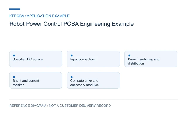
Illustrative engineering application example, not a KFPCBA customer delivery or measured production record. The configuration, calculations and record examples below are hypothetical planning inputs requiring project-specific review.
Requirements for a robot power-control board
This example considers a low-voltage DC distribution board between a specified supply and separate drive, compute and accessory modules. Its purpose is to connect and supervise power branches. It is not a battery charger, traction inverter or robot emergency-stop design. Start with the supply source, connector polarity, steady operating demand, startup behavior, returned energy and branch-enable responsibilities. List the actual downstream modules rather than assuming a single robot power requirement.
Specify which module may start first, which may restart automatically and which must remain disabled after a fault. A compute module may need to log a branch trip even when a motor module is disconnected. The schematic and state diagram should therefore agree on auxiliary power, enable signals, feedback and reset behavior. Wiring and firmware revisions form part of the electrical interface.
Design constraints and the monitor-versus-protection decision
Do not treat a current-monitor reading as a complete protective function. The TI INA226 documentation describes a shunt-based monitor reporting current, bus voltage and power through I2C/SMBus, with an alert function. A monitored branch still needs a separately engineered disconnect and fault-response strategy where required. Update time, firmware scheduling and switch behavior must be evaluated together.
Review startup charging and module input capacitance independently from normal running current. Connector contact count, cable gauge, board copper and mechanical retention must be selected from the actual duty profile and installation. A downstream drive that returns energy may also affect the upstream supply. Document whether that behavior is allowed and how the system handles it; a board photograph cannot resolve the question.
Reference configuration and a shunt calculation
| Function | Reference block | Boundary |
|---|---|---|
| Input | Keyed supply connection and defined input network | Supply and battery functions external |
| Branches | Separately identified compute, drive and accessory connections | Each load profile still required |
| Monitoring | Shunt, monitor and controller | Measurement is not a complete disconnect path |
| Control | Enable commands, status and fault logging | Robot safety architecture external |
Hypothetical calculation: for a branch carrying 3 A through a 0.010 Ω shunt, the drop is I × R = 3 × 0.010 = 0.030 V. Dissipation is I²R = 3² × 0.010 = 0.090 W. These nominal values illustrate the measurement tradeoff only. Pulse loading, tolerance, temperature rise, land pattern and allowed voltage loss must govern the selected part and its derating.
Procurement and mixed-technology assembly choices
Freeze the shunt resistance, tolerance, package and sensing connection in the BOM. A mechanically compatible resistor with a different value changes firmware scaling. Power switches and connectors require controlled alternates because their losses, terminal arrangement or mounting geometry may differ. Keep signal headers visually and mechanically distinguishable from power inputs whenever the design allows it.
Define whether the order covers board soldering, finished-harness mating or harness manufacture. Cutting, crimping, pull evaluation and wire identification need explicit specifications if requested. Mark terminal seating, fasteners and cable strain relief on the drawing. Discuss heat-sensitive parts and large connector insertion during assembly preparation; the process plan must follow the released component data.
Verification matrix for branches and sequencing
| Stimulus | Observe | Record |
|---|---|---|
| Initial power application with dummy loads | Auxiliary supply and enable order | Input waveform, firmware and sequence timestamps |
| Known branch current | Monitor conversion and scaling | Reference current, raw reading and calculated value |
| Controlled branch-fault simulation | Specified response and unaffected-branch behavior | Fault source, event timing and restart policy |
| Power removal and restoration | Stored state and enable behavior | Reset cause and resulting branch states |
Use purpose-built fixtures and approved fault methods rather than improvised short circuits. A test-scope discussion should identify loads, waveform capture, current references and the conditions that require a full robot test. Board checks cannot establish motion safety, battery compatibility or a complete system thermal envelope.
Handoff documents and a branch record
Release the branch map, mating-connector list, power budget, schematics, PCB data, assembly files, firmware hash and test procedure together. Include the mechanical model when busbars, heatsinks, standoffs or cable bends affect installation. Define test-fixture revisions and instrument identification so a changed load arrangement is visible.
An example record template is: serial; hardware revision; branch ID; load-emulator setting; reference current; monitor value; enable timestamp; fault identifier; restart observation; disposition. These fields are proposed, with no measured result implied. Submit the controlled package through a project inquiry and assign sourcing, harness and module-assembly responsibilities before quotation.
Three planning scenarios
A replacement compute module has the same running demand but fails at startup. What changes?
Obtain its startup current and input-capacitance information. Review the source, branch switch and sequencing with that profile, then repeat the startup test using a representative load instead of accepting steady demand as sufficient.
The current reading doubles after a sourcing substitution. Where should the review start?
Compare the installed shunt value, sense routing, monitor configuration and firmware calibration with the approved revision. Record the substitution; do not hide the mismatch by changing a displayed number without review.
Can a finished cable be included without commissioning harness production?
Yes, if the scope explicitly identifies a supplied cable and mating operation. Specify its part number, orientation and retention check. Custom cutting or crimping remains a separate manufacturing task.
Source material and applicable scope
- Texas Instruments INA226 product documentation. Checked 11 November 2026. The product page describes high-side or low-side sensing, configurable averaging and an alert function; it does not describe a complete robot branch-disconnect design. Applies to shunt-based current, voltage and power monitoring with a digital interface. This source does not document a KFPCBA build, production result, approved BOM or complete-product compliance.