PCB ASSEMBLY · ELECTRONIC ASSEMBLY
Robot Vacuum Control PCBA Engineering Example
Engineering Application Example
Illustrative robot-vacuum control PCBA example covering sensor status, drive commands, optical integration and revision-controlled tests.
Illustrative engineering application example, not a KFPCBA customer delivery or measured production record. The configuration, calculations and record examples below are hypothetical planning inputs requiring project-specific review.
Requirements for a robot-vacuum controller
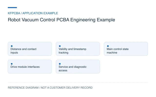
This example separates a robot-vacuum main board into sensing, drive requests, user controls and service access. The assumed board receives distance and contact information and coordinates commands to defined motor-driver modules. Navigation quality, cleaning coverage, suction performance and autonomous operation are not established by this block arrangement. Begin with an interface schedule identifying every sensor, its connector, supply, message format, update rate and invalid-data indication.
State whether wheel control, brush control and suction control reside on the main board or in external modules. Define which device owns the motion command when data becomes stale or a peripheral restarts. A valid sensor reading, a valid communication packet and permission to move are three different states. Recording them separately makes fault analysis more useful than a single general error flag.
Design constraints and the optical integration decision
A time-of-flight sensor is one possible input, not a complete obstacle or drop-detection system. The ST VL53L1X documentation describes a ranging device with an I2C interface, shutdown and interrupt pins, and programmable receive region of interest. These features support planning sensor access and status handling. They do not establish detection coverage in a moving vacuum.
Optical position, cover-window design, contamination and assembly handling need their own instructions. Avoid placing a cable or enclosure rib in the intended field of view. If several identical sensor modules share a bus, define their startup and addressing scheme from the chosen component documentation. Also define sensor power sequencing so a reset peripheral cannot be mistaken for a fresh, valid reading.
Reference configuration and a stale-data calculation
| Block | Reference task | Separate evidence required |
|---|---|---|
| Sensor inputs | Read range, contact and module status | Installed optical and mechanical behavior |
| Controller | Timestamp data and coordinate commands | State-machine and timing review |
| Drive interfaces | Send requests and read module faults | Motor, gearing and load characterization |
| Service access | Program firmware and export diagnostics | Approved production and recovery process |
Hypothetical calculation: assume a sensor publishes every 40 ms and the application marks data stale after three consecutive missed publications. The nominal stale interval is 3 × 40 = 120 ms. At an assumed travel speed of 0.20 m/s, the robot could move 0.20 × 0.120 = 0.024 m, or 24 mm, during that interval. Scheduling delay and mechanical stopping distance are additional. This arithmetic exposes a requirements question; it is not a safe stopping-distance specification.
Assembly and procurement choices
Decide whether optical sensors are soldered directly to the main PCB or purchased as separately connected modules. A module simplifies some board operations but introduces a harness, mounting tolerance and another revision-controlled item. Direct assembly requires component-specific handling and an optical keepout consistent with the final housing. The BOM should identify the exact option and any removable protective film instructions.
Use unique connector identifiers for wheel, brush, sensor and charging-related interfaces. A common housing family does not mean the pinouts are interchangeable. Define mating plugs and cable routing on the assembly drawing, including access to service and programming points after installation. Review mixed-technology parts through SMT assembly preparation, with separate insertion instructions for applicable through-hole connectors.
Verification matrix for data and commands
| Scenario | Method | Evidence to capture |
|---|---|---|
| Sensor identification and mapping | Activate one input at a time | Physical connector, reported channel and timestamp |
| Missing or invalid range | Use the approved simulator or sensor fixture | Validity transition and resulting command state |
| Drive-module fault | Inject the defined fault message | Controller state and recovery request |
| Peripheral restart | Reset a selected module under the procedure | Startup sequence, stale flag and accepted first sample |
Bench simulations can check wiring, protocol handling and software decisions. Representative installed tests must separately address surfaces, lighting, obstructions, contamination and movement. A product-test plan should state which of these are requested, who supplies the robot fixture and how raw diagnostics are retained. An assembled board is not evidence of coverage across a household environment.
Handoff documents and a sensor-event record
Supply the PCB files, BOM, placement data, assembly drawing, connector schedule, optical mounting drawing, firmware hash and protocol versions. Include calibration ownership and explain whether coefficients belong to a sensor module, board serial or complete robot. Maintain separate part numbers when optical geometry changes, even if the electrical connector remains identical.
A proposed event record is: board serial; firmware hash; input ID; sample timestamp; raw status; interpreted validity; drive request; module fault; recovery event; test disposition. Do not populate assumed pass results. Use an engineering RFQ to request board assembly and define any sensor-module mounting, programming or installed-system tests as named line items.
Three planning scenarios
A sensor works without its cover but misbehaves in the housing. Is the PCB necessarily faulty?
No. Compare the optical opening, cover material, sensor placement and contamination with the component integration requirements. Retain raw status and distance data before adjusting application thresholds.
Two peripherals use identical connectors. How can assembly distinguish them?
Use explicit interface IDs, pin tables and harness labels, and consider mechanical keying where practical. Validate the finished routing against the drawing rather than relying on cable color alone.
Can simulated sensor packets prove collision avoidance?
They can exercise controller logic under defined messages. Physical detection, processing delays and mechanical response still need representative system testing under an approved product validation plan.
Source material and applicable scope
- STMicroelectronics VL53L1X product documentation. Checked 11 November 2026. The public page lists I2C, shutdown and interrupt pins, a programmable receive region and component integration resources; these are not robot-vacuum detection results. Applies to a possible ranging-device interface, shutdown/interrupt access and receive-region configuration. This source does not document a KFPCBA build, production result, approved BOM or complete-product compliance.