PCB ASSEMBLY · ELECTRONIC ASSEMBLY
FFU Fan Controller PCBA Engineering Example
Engineering Application Example
Illustrative filter fan unit controller PCBA example covering fan command and feedback interfaces, daughterboard fit and module-test boundaries.
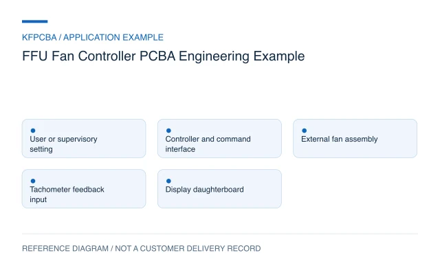
Illustrative engineering application example, not a KFPCBA customer delivery or measured production record. The configuration, calculations and record examples below are hypothetical planning inputs requiring project-specific review.
Requirements for a filter fan unit controller
This example concerns a signal-control module for a filter fan unit, or FFU. It sends a speed request to a separately specified fan assembly and reads defined feedback. It does not assume the board contains the fan's motor inverter. Obtain the fan manufacturer's interface document before selecting command circuitry: an analog request, PWM input and serial command are different electrical and software requirements.
List the user-setting interface, supervisory connection, fan-feedback output and any display daughterboard. Define who owns startup, local override and lost-command behavior. If multiple FFUs operate together, state whether this board controls one unit or a group. Airflow uniformity, filter condition, acoustic performance and room cleanliness require equipment or installation evidence beyond board assembly.
Design constraints and the command-versus-feedback decision
A speed command is not proof that the fan reached the requested state. The TI AMC6821 documentation provides a component example combining PWM output and tachometer monitoring, including distinct control modes. It supports the architectural distinction between a commanded duty cycle and observed rotation. It is not an FFU reference design and does not establish compatibility with a selected industrial fan.
Specify command polarity, signal reference, frequency where relevant, feedback pulse format and disconnected-line behavior using the actual fan data. A non-rotating fan and an absent feedback wire may look similar to a pulse counter, so the product owner must define the diagnostic limits. Keep fan power connections distinct from low-level command and display interfaces in the schematic and assembly drawing.
Reference configuration and a tachometer calculation
| Block | Reference role | Required input |
|---|---|---|
| User or supervisory input | Provide the requested operating setting | Authority and override rules |
| Controller and fan interface | Generate the selected fan command | Manufacturer interface definition |
| Feedback input | Count pulses and report status | Pulse count and electrical format |
| Display daughterboard | Show settings and diagnostics | Connector, mounting and firmware contract |
Hypothetical calculation: assume the specified fan produces two tachometer pulses per revolution and the controller measures 60 pulses per second. Rotational speed is 60 ÷ 2 × 60 = 1,800 revolutions per minute. The pulse count must come from the actual fan documentation. Even a correct speed result is not an airflow measurement; filter loading and system resistance require separate evaluation.
Mixed-technology assembly and procurement choices
Define whether the control and display boards are separate assemblies or one delivered module. A shared interboard connector requires agreement on mating direction, stack height, standoffs and tolerance. Identify large through-hole parts by seating height and orientation. Review whether their leads, connectors or fasteners obstruct another board after the module is assembled.
Procurement should control connector series and mating parts, not only pitch and pin count. An alternate can change latch position or stack height. Mark module-level hardware and any cable separately in the BOM so it is not silently omitted from a board-only order. Use DFMA preparation to review insertion, soldering access, mounting order and inspection access for the actual assembly.
Verification matrix for the board and assembled module
| Condition | Check | Record |
|---|---|---|
| Defined command settings | Measure the interface output against the fan specification | Setting, signal waveform and configuration |
| Known feedback pulse input | Compare calculated speed with the simulator | Pulse rate, pulses per revolution and displayed value |
| Feedback removed | Observe the agreed diagnostic and command policy | Event timing, status and recovery |
| Control/display assembly | Check mating, hardware and display mapping | Module revision and mechanical observations |
A pulse simulator can establish scaling without running a fan. A representative fan test is separately needed for command compatibility, startup and feedback behavior. A full FFU test adds the installed housing, filter and airflow measurements. Describe these stages explicitly in the test scope, including who supplies each fixture and what evidence is retained.
Handoff documents and an example module record
Supply PCB and assembly files for both boards, the fan interface document, interboard pin table, module drawing, firmware hashes and test procedure. Include user-setting units and any conversion between a displayed percentage and the actual fan request. Specify whether calibration or installation settings are stored on the main board, daughterboard or supervisory device.
A proposed record template is: main-board serial; daughterboard revision; firmware hashes; fan-interface variant; requested setting; measured command; simulated pulse rate; calculated speed; diagnostic state; disposition. Values in that template are not results. Submit the package through a project inquiry and separately identify fan supply, module assembly, airflow measurement and installation commissioning.
Three planning scenarios
The fan rotates but the display shows zero speed. What should be checked?
Compare the actual feedback format, pinout, pulse count and controller configuration with the released interface document. Verify the input signal at the approved test point before changing the speed formula.
Can equal rotational speed prove equal airflow across two FFUs?
No. Fan characteristics, housing, filter loading and system resistance can differ. Use the specified equipment-level airflow method and keep its results separate from tachometer scaling.
A connector alternate mates electrically but the boards do not fasten together. Is it an acceptable substitute?
Review stack height, latch geometry, locating features and standoff positions. The alternate must satisfy the mechanical assembly as well as the electrical pin assignment before approval.
Source material and applicable scope
- Texas Instruments AMC6821 product documentation. Checked 11 November 2026. The public page describes PWM fan control, tachometer monitoring and selectable control modes; its listed applications do not establish an FFU design or fan-interface compatibility. Applies to the component-level distinction between PWM command, tachometer feedback and control modes. This source does not document a KFPCBA build, production result, approved BOM or complete-product compliance.