PCB ASSEMBLY · ELECTRONIC ASSEMBLY
Central Temperature Controller PCBA Engineering Example
Engineering Application Example
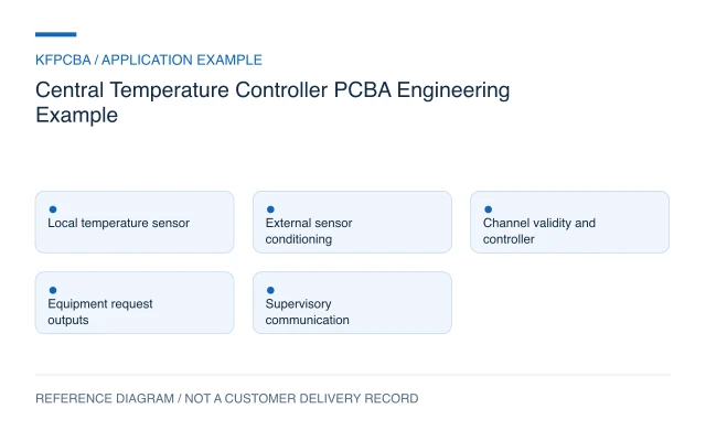
Illustrative central temperature-controller PCBA example covering local sensing, external sensor interfaces, output mapping and communication timing.
Illustrative engineering application example, not a KFPCBA customer delivery or measured production record. The configuration, calculations and record examples below are hypothetical planning inputs requiring project-specific review.
Requirements for a central temperature controller
Begin with a channel schedule rather than the label HVAC. For this example, a controller collects local board temperature and several externally conditioned temperature inputs, exchanges status with a supervisory unit and sends operating requests to separate equipment. It does not directly establish a compressor drive, heating-power stage or building control certification. The product owner must define each sensor type, installation location, update interval, output state and response to missing data.
Record the difference between room temperature, duct temperature and controller-board temperature. A board-mounted sensor near a regulator can report local heating rather than the controlled space. Mounting, airflow and enclosure openings therefore belong in the requirements. Specify whether a communication timeout preserves a last command, requests shutdown or transfers authority to another controller; the appropriate behavior depends on the equipment.
Design constraints and the sensing decision
A local digital sensor and a remote cable probe solve different problems. The TI TMP117 product documentation identifies an I2C/SMBus temperature sensor with programmable alert functionality. That supports considering a local sensing block; it does not justify extending a board-level bus along an arbitrary field cable. For a remote probe, define the transducer, cable, protection, conditioning and calibration method independently.
Separate low-level acquisition return paths from pulsed output currents during layout review. Define sensor connector pin order and the allowed disconnected state before selecting pull resistors. A terminal labelled temperature is insufficient when one option expects a resistance and another expects a powered signal. Keep these as distinct BOM variants with visibly different assembly instructions.
Reference configuration and a timing calculation
| Block | Planning choice | Decision still required |
|---|---|---|
| Local sensing | Digital board-temperature channel | Placement and local heat bias |
| External inputs | Defined conditioned sensor channels | Probe technology and cable interface |
| Controller | Channel validity and timestamp tracking | Filter and stale-data policy |
| Outputs and link | Equipment requests plus supervisory status | Electrical interface and message ownership |
Hypothetical calculation: assume four input transactions each occupy 6 ms, with no overlap, and a complete scan is scheduled every 200 ms. Acquisition occupies 4 × 6 = 24 ms, or 24 ÷ 200 × 100 = 12% of that interval. The remaining 176 ms is scheduling space, not proof that firmware meets its deadlines. Conversion delays, retries and communication service time must be added to the real timing budget.
Assembly and procurement choices
Release a BOM that distinguishes sensor-interface accuracy requirements from connector and output requirements. Permit an alternate only after reviewing its electrical behavior, package, pinout and software consequences. Matching footprints alone cannot preserve a calibrated acquisition chain. Mark precision resistors, option links and polarity-sensitive parts on the assembly drawing.
For mixed SMT and through-hole assembly, identify terminal orientation, probe-access points and components that obstruct insertion or soldering. Decide whether terminal blocks arrive on the board or as a separately packed mating part. A DFMA review can organize those questions before a build request. Cleaning, coating and sensor venting require their own material and process instructions rather than an application-name assumption.
Verification matrix for the proposed functions
| Condition | Method | Record and acceptance basis |
|---|---|---|
| Known sensor input | Apply an agreed reference or simulator | Raw value, converted value and requirement limit |
| Open or invalid input | Use a specified fault adapter | Validity flag, output response and recovery sequence |
| Communication interruption | Pause supervisory messages | Timeout event and agreed command policy |
| Output transition during acquisition | Capture input data and output timing together | Disturbance and settling against the design budget |
Allocate board checks and installed-system checks separately. Simulated inputs can verify channel mapping and software scaling, but they do not establish the accuracy of a probe installed in a duct. A proposed product-test scope should name the fixtures, firmware and external equipment needed to close that gap.
Handoff files and an example record
Provide PCB manufacturing data, BOM, placement file, assembly drawing, sensor schedule, protocol definition, firmware hash and test procedure from one approved revision. Include correction coefficients only with their generation method and storage location. The example record structure is: board serial; hardware revision; firmware hash; channel ID; stimulus reference; raw code; converted value; timestamp; validity; disposition. A blank disposition means not evaluated, not passed.
Use the engineering RFQ to define quantities, sourcing responsibility and the requested evidence. Keep board assembly, probe supply, control tuning and complete installation commissioning as separately described deliverables.
Three planning scenarios
The remote probe changes from a thermistor to a digital module. Can the BOM alone change?
No. Recheck the input circuit, cable interface, supply, connector pinout and firmware conversion. Give the new channel a distinct configuration identifier so an old test fixture cannot silently apply the wrong stimulus.
The board reads correctly on the bench but drifts inside its enclosure. What is the next comparison?
Compare board temperature, external reference temperature, airflow and output activity at the same timestamps. This helps distinguish local self-heating from probe scaling before changing calibration coefficients.
A supervisor becomes unavailable during a scan. Should the controller keep the last setting?
That is a product requirement, not an assembly default. Specify a bounded stale-data policy and test the loss and restoration of communications while sensor acquisition continues.
Source material and applicable scope
- Texas Instruments TMP117 product documentation. Checked 11 November 2026. The public product page lists I2C/SMBus compatibility and programmable alerts; it is a component reference, not an HVAC system design. Applies to the local digital-sensor interface and alert concept. This source does not document a KFPCBA build, production result, approved BOM or complete-product compliance.