PCB FABRICATION · ENGINEERING EXAMPLE
Metal-Core Electric-Drive PCB Thermal Example
Engineering Application Example
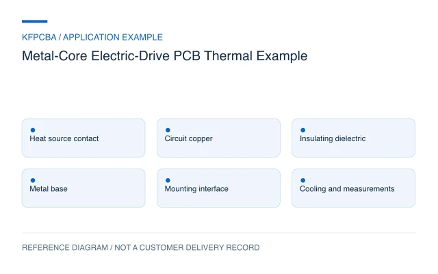
Assess an electric-drive metal-core PCB through the complete heat path, from the component contact through the dielectric and mounting interface to the cooling structure.
Illustrative engineering application example, not a KFPCBA customer delivery or measured production record. The configurations and calculations below are hypothetical design-review inputs. Project acceptance requires approved drawings and named engineering review.
Evaluate the complete heat path
An insulated metal substrate can provide a useful board-level thermal path for selected electric-drive electronics. Its value depends on the dielectric, copper geometry, component contact, metal base and interface to the cooling structure. The words aluminum-core do not define operating temperature, allowable current or electrical insulation.
This example concerns a thermal PCB concept for an electric-drive subsystem. It does not describe a qualified traction power module or prove that an IMS board can replace another substrate in an existing design. A single-circuit-layer structure is one possible input; the electrical topology and thermal boundary conditions determine whether it is appropriate.
Define where heat enters and leaves the board
List the heat sources and their estimated loss in each operating state. Identify component contact areas, electrical potentials, mounting holes, cooling surfaces and any insulating hardware. Specify the external cooling boundary, including the enclosure or heat sink and the way the board is clamped to it.
Keep the electrical circuit and the metal base distinct in the drawing. Define whether the base has an intentional electrical connection and how exposed metal and holes are treated. The design owner must supply the relevant insulation and mounting requirements; they cannot be inferred from the base metal or an unrelated laminate Tg value.
Compare dielectric systems using more than conductivity
Ventec's VT-4BC data sheet reports conductivity, thickness-dependent thermal impedance and separately described electrical test properties, with conditions and typical-value limitations. This supports comparing a complete material construction rather than ranking materials by a single conductivity number. It does not prescribe VT-4BC for this board or confirm KFPCBA uses it.
For the proposed review, request the exact dielectric grade and thickness, copper definition, metal alloy and base thickness. Compare the units and measurement method before using a supplier's thermal value in a model. An area-normalized impedance must not be inserted into a K/W resistance budget without the appropriate geometry and assumptions.
A hypothetical series thermal-resistance budget
Assume a simplified single heat path has the following provisional resistances: source contact 1.0 K/W, dielectric region 0.6 K/W, mounting interface 0.4 K/W and cooling structure to ambient 1.5 K/W. The sum is 3.5 K/W. For an assumed 6 W flowing through that path, the modeled temperature difference is ΔT = P × R = 6 × 3.5 = 21 K.
If only the dielectric contribution falls from 0.6 to 0.3 K/W, the total becomes 3.2 K/W and the modeled difference becomes 19.2 K. The reduction is 1.8 K. This shows how another part of the path can limit the benefit of a material change.
All values are hypothetical. The model excludes heat spreading, parallel paths, transient behavior and temperature dependence. It does not predict a semiconductor junction temperature or an allowable operating point. Validate the model structure and boundary conditions before applying measured or supplier data.
Treat mounting quality as a thermal design input
A favorable dielectric specification cannot correct an uncontrolled contact surface. Define flatness, burr control, mounting-hole geometry, interface material and the clamping method together with the mechanical engineer. Review whether assembly tolerances create a gap or concentrate force near a component or exposed edge.
For a single-layer IMS proposal, also prove that the required circuit routing and test access fit the available conductor layer. A thermally convenient footprint is not useful if it compromises the electrical path. Use the aluminum PCB review page to discuss the full proposed construction and its inspection needs.
Verify the board, interface and cooling arrangement
| Subject | Agreed check | Evidence to retain |
|---|---|---|
| Board construction | Material identity, dimensions and electrical test | Lot, stack definition and measured features |
| Mounting contact | Surface and installed-fit inspection | Interface material, fixture and assembly method |
| Thermal path | Defined heat input and steady/transient observations | Ambient, cooling state and sensor locations |
| Electrical separation | Design-owner-approved inspection and test plan | Method, conditions and acceptance decision |
Compare candidate boards under the same mounting and cooling conditions. Temperature images alone may be misleading without surface emissivity and sensor correlation. Keep raw temperatures and the measurement arrangement, not merely a colored image or a pass statement.
Hand over the thermal boundary conditions
The package should include fabrication and assembly data, the exact IMS material definition, base treatment, hole and edge requirements, interface specification and mounting drawing. Add the loss assumptions, thermal model, measurement positions and cooling configuration. Identify which values are preliminary estimates and which come from an agreed test.
Start with the intended circuit, heat-source locations and available cooling surface. Send available drawings through the quotation request so the material, manufacturing and verification scope can be assessed for the actual design.
Electric-drive IMS questions
Does higher thermal conductivity always produce a cooler board?
No. Dielectric thickness, spreading and the remaining interfaces affect the complete heat path. Compare an equivalent construction and mounting arrangement.
Can the aluminum base be assumed to be circuit ground?
No. Define its electrical role and connection explicitly. Mechanical contact with a housing is not a substitute for an approved circuit and insulation definition.
Does a Tg value define insulation or current rating?
No. Tg is one material property. Electrical separation, current-path behavior and temperature under the intended conditions require their own requirements and evidence.
Source material and applicable scope
- Ventec International Group — VT-4BC Metal Base Laminate Data Sheet. Supports distinguishing conductivity, thickness-dependent thermal impedance and separately conditioned electrical properties; no material value is adopted as this board's performance. These sources do not establish KFPCBA delivery or capability.