PCB FABRICATION · ENGINEERING EXAMPLE
Portable Automotive Power PCB Engineering Example
Engineering Application Example
Define the energy source, charging and output modes before deciding how a portable automotive power PCB should route current and manage heat.
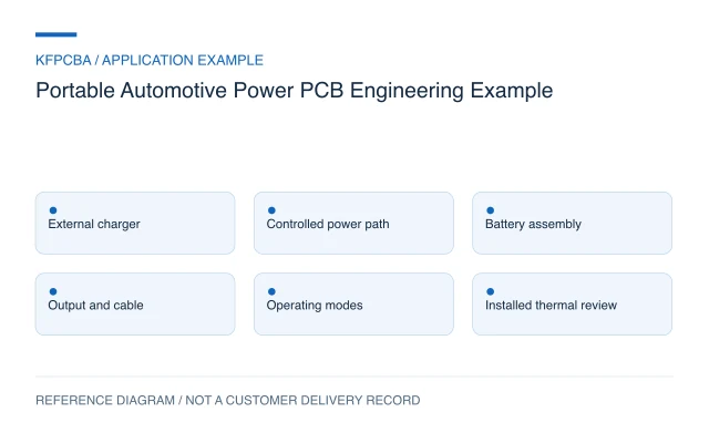
Illustrative engineering application example, not a KFPCBA customer delivery or measured production record. The configurations and calculations below are hypothetical design-review inputs. Project acceptance requires approved drawings and named engineering review.
Define the portable power function precisely
A portable power unit used around a vehicle may power accessories, charge devices or serve a dedicated load. These functions have different connectors, operating sequences and verification needs. Begin with the input source, stored energy and output modes instead of treating the phrase automotive power supply as an electrical specification.
This example addresses a rechargeable portable power PCB. It does not describe an engine jump starter or authorize direct connection to an unspecified vehicle circuit. A heavy-copper multilayer board is a candidate design approach, not proof of a particular output current or vehicle qualification.
Map charging, discharging and idle separately
Draw a state table for charging from an external adapter, battery-powered output, idle storage and startup. Add simultaneous charging and output only if the architecture is intended to permit it. Identify who controls each power path and what happens when a cable is removed, a load is attached or the battery is unavailable.
The PCB brief should include the battery assembly interface, output connector ratings supplied by the designer, enclosure ventilation or heat-contact provisions and firmware configuration. A power connector's nominal marking does not describe the loss or temperature of its complete installed connection. Record cable and mating-part revisions with the board.
A hypothetical runtime budget
Assume a battery assembly is described for this exercise as 14.4 V nominal and 4 Ah. Nominal stored energy is 14.4 × 4 = 57.6 Wh. If a provisional usable-energy factor of 85% is assumed for the whole path, the output-energy budget becomes 57.6 × 0.85 = 48.96 Wh. At a constant 24 W load, estimated runtime is 48.96 ÷ 24 = 2.04 hours.
These assumptions are not measured efficiency, battery capacity or a runtime promise. Actual usable energy depends on the discharge profile, cutoff strategy, temperature, battery condition and conversion losses. A variable load requires energy integration over its operating states. The exercise is useful for spotting a mismatch between the desired runtime and the proposed energy source before PCB details are frozen.
Keep switching and measurement paths identifiable
The BQ25703A data sheet gives device-specific placement priorities for a buck-boost charger, including compact high-frequency loops, short gate-drive paths and dedicated sense routing. It illustrates why component placement matters alongside conductor thickness; the exact circuit and limits must follow the chosen controller.
For the proposed review, color-code the charging current, discharge current, switching nodes and low-level feedback on separate overlays. Check each mode because the dominant current path can change. Locate connector bottlenecks and interlayer transitions before widening a large copper area that may not be the limiting part of the path.
Use heavy copper where the complete path benefits
Increasing conductor cross-section can reduce resistance, but the benefit can be lost at narrow necks, vias, shunts or connector contacts. Define finished copper by layer and region, with an agreed fabrication tolerance. A six-layer construction or a shorthand such as 3 oz is only a proposed input until the full stackup and routing have been reviewed.
Evaluate the effect on fine-feature spacing, soldering heat demand and the ability to assemble large terminals without overheating nearby components. Compare the complete cost and verification scope through the thick-copper PCB review. Do not assign an allowable current from copper weight alone.
Verify transitions as well as steady output
| Operating condition | Observation to plan | Record to retain |
|---|---|---|
| Battery-powered output | Input and output energy under a defined load | Load profile, cutoff settings and energy readings |
| Charging | Path temperatures and configured charge behavior | Adapter, battery interface and settings |
| Connection changes | Output and control-state transitions | Waveforms, cable versions and event sequence |
| Installed operation | Connector and board temperatures in the enclosure | Mounting, ambient conditions and sensor locations |
Agree operating limits and abnormal-condition procedures with the system owner. A stable bench output during one state does not establish the behavior of every startup, charging or storage state.
Keep the energy assumptions in the handoff
Supply fabrication data, finished-copper definitions, assembly drawings, approved components and the mode table. Add firmware configuration, the battery-interface definition, connector and cable requirements and the thermal arrangement. The acceptance plan should identify whether energy, transitions and temperature are measured on the bare board or on the final assembly.
For an initial assessment, state the load, intended runtime and charging method. Submit current design files through the engineering RFQ so the manufacturing scope and missing system inputs can be reviewed.
Portable power PCB questions
Can battery amp-hours alone predict runtime?
No. Include voltage to estimate nominal energy, then account for the actual usable-energy profile and load. Compare watt-hours under stated conditions rather than capacity labels alone.
Will thick copper prevent connector heating?
Not necessarily. Contact resistance, mating quality, cable termination and local airflow may dominate. Evaluate the installed connection together with the board path.
Can a portable accessory supply also be called a jump starter?
Only if its separate high-current architecture and intended function have been defined and verified. That function is outside this illustrative rechargeable accessory-power example.
Source material and applicable scope
- Texas Instruments — BQ25703A Data Sheet, SLUSCU1A. Section 11 supports the device-specific placement discussion of switching loops, gate-drive paths and current-sense routing. It does not establish vehicle compatibility or runtime. These sources do not establish KFPCBA delivery or capability.