PCB FABRICATION · ENGINEERING EXAMPLE
Semi-Flex Steering-Control PCB Layout Example
Engineering Application Example
Assess a semi-flex steering-control board as an installation-geometry problem, with an explicit bend state, mechanical support and controlled assembly sequence.
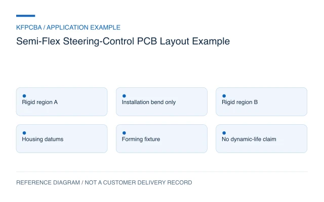
Illustrative engineering application example, not a KFPCBA customer delivery or measured production record. The configurations and calculations below are hypothetical design-review inputs. Project acceptance requires approved drawings and named engineering review.
Use semi-flex for a defined installation geometry
A semi-flex concept may connect two circuit-bearing regions that must occupy different planes inside a housing. Its suitability depends on the construction and the installation motion, not simply on the control function printed on the schematic. The first question is whether bending occurs only during assembly or repeatedly during operation.
This steering-control packaging example is strictly a board-level reference. It does not establish steering availability, fault tolerance or suitability for steer-by-wire production. A four-layer rigid-region concept is an optional design input; the bend region needs a separate, explicit construction definition.
Write down every intended movement
Describe the flat manufacturing state, any intermediate assembly positions and the final installed state. Name the bend direction, bend line, required angle, support locations and expected handling sequence. Include rework and service movements rather than treating the first installation as the entire mechanical history.
Check how the housing locates each rigid region. Two independent fastening points can impose displacement on the connecting region if their tolerances are not coordinated. The mechanical review should show whether the housing supports the installed shape or leaves the bend carrying a continuing load. Actual movement and vibration requirements belong in the system owner's specification.
A hypothetical bend-length calculation
For a geometry exercise, assume a 90-degree bend with a reference-path radius of 8 mm. Arc length is L = R × θ, with θ in radians. Therefore L = 8 × π/2 ≈ 12.57 mm. If the sketch reserves 3 mm of straight approach at each end, the initial reference-path length becomes 12.57 + 3 + 3 = 18.57 mm.
The 8 mm radius is an assumed geometry, not an approved minimum. The calculation excludes the actual neutral-axis position, material thickness, transition details and tolerances. Its purpose is to expose a packaging conflict before manufacture: a short connecting region cannot be accepted merely because the folded 3D view looks plausible. The manufacturer and design owner must agree the construction-specific bend limits.
Name the semi-flex technology being proposed
Würth Elektronik's SEMI.flex rules describe a particular deep-milled rigid-material construction for flex-to-install use, including controlled bending and defined direction. That is evidence that semi-flex must be discussed as a construction-specific technology. It does not make every partially flexible board equivalent or establish a KFPCBA capability.
For this proposed review, replace ambiguous terms such as flexible PP with a cross-section. Identify which layers remain in the bend, residual thickness, material system, mask or coverlay and transition shape. Show the proposed bend zone on copper and mechanical layers. Do not transfer another supplier's published radius or cycle allowance to a different construction without agreement.
Design the handling method with the board
The assembly concept should identify where a fixture holds the rigid regions, where forming force is applied and how the intended shape is checked. Keep connector insertion forces and fastening operations in that sequence. Repeated manual adjustment to make the board fit is a sign that the geometry or locating scheme needs review.
Discuss panel support, component access, depaneling and handling protection during the rigid-flex and semi-flex review. A board delivered flat and a board delivered preformed create different packing and inspection needs. State which condition is requested and how it will be represented in the drawing set.
Verify the flat board and the installed shape
| Risk | Review or check | Evidence to retain |
|---|---|---|
| Wrong bend construction | Drawing and agreed cross-section checks | Residual thickness, region and revision |
| Installation requires over-forming | Trial assembly with controlled tooling | Fixture, sequence and final geometry |
| Connection changes after forming | Agreed before/after electrical checks | Netlist results and visual observations |
| Housing forces the regions apart | Installed tolerance and support review | Mechanical datums and measured fit |
The project must also define any environmental or functional tests and their owners. A successful fold and continuity check do not validate a steering-control function or repeated operating motion.
Deliver the forming definition with fabrication data
Provide the flat outline, final installed drawing, bend-zone cross-section, angle and reference radius, rigid-region datums and forming sequence. Add assembly data, material definitions, permitted handling events and the agreed inspection plan. Identify whether components, coatings or mounting hardware restrict access during forming.
For an initial assessment, a housing sketch and the required relationship between the rigid regions are useful. Submit them through the quotation request, with the intended movement stated clearly, so the construction and review scope can be discussed.
Semi-flex control-board questions
Can the bend act as a hinge during steering operation?
That requires a different motion and life assessment. This example considers controlled installation geometry only and supplies no dynamic-flex qualification.
Can a four-layer label describe the bend region?
Not completely. The rigid and bend regions can have different retained layers and thicknesses. Provide a region-by-region cross-section and layer connectivity.
Should an installer correct a fit issue by bending it again?
Unplanned reforming changes the handling history. Stop the assembly review at that discrepancy and resolve the drawing, tolerance or forming process before accepting the configuration.
Source material and applicable scope
- Würth Elektronik — Design Rules SEMI.flex. The stated supplier construction supports distinguishing flex-to-install semi-flex from repeated flexing and shows why bend direction and controlled forming need definition. Its numeric limits are not adopted. These sources do not establish KFPCBA delivery or capability.