PCB FABRICATION · ENGINEERING EXAMPLE
Rigid-Flex Steering-Sensor PCB Engineering Example
Engineering Application Example
Use rigid-flex to connect a located sensor region to a separate electronics region while controlling sensor datums, flex loading and installed geometry.
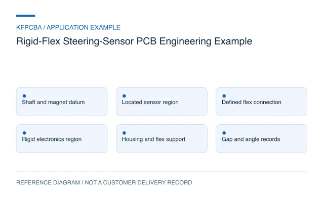
Illustrative engineering application example, not a KFPCBA customer delivery or measured production record. The configurations and calculations below are hypothetical design-review inputs. Project acceptance requires approved drawings and named engineering review.
Keep the sensor datum independent of the flex connection
A rigid-flex steering-sensor concept can place the sensing circuit in one rigid region and supporting electronics in another. The flexible connection accommodates the packaging arrangement. It should not be assumed to locate the sensor accurately or to absorb an undefined assembly displacement.
This is a board-level engineering example, not a qualified steering sensor or evidence of a delivered product. A four-layer rigid-region proposal and a polyimide flex connection are possible design inputs. They do not define the number of copper layers in the flex, its bend life or the accuracy of the assembled sensor.
Identify what establishes the measurement geometry
For a magnetic-angle sensing concept, define the magnet, shaft axis, sensor location, mounting datums and relevant gaps in one mechanical coordinate system. The sensor's active location may differ from the package outline. Use the actual device drawing and magnet specification, then show how the rigid board region is constrained in the housing.
TI's angle-sensing application note discusses the effects of magnet selection, sensor placement and mechanical alignment on measured angle. It supports treating geometry as part of the measurement chain. It does not establish accuracy for this proposed steering-sensor arrangement or replace a system-specific calibration and verification plan.
A hypothetical mechanical tolerance budget
Assume three independent drawing contributions are bounded as follows: PCB locating feature ±0.10 mm, housing locator ±0.15 mm and sensor placement ±0.05 mm along one selected direction. A conservative worst-case sum is ±(0.10 + 0.15 + 0.05) = ±0.30 mm. For a nominal 0.80 mm geometrical gap in this exercise, the calculated interval is 0.50 to 1.10 mm.
This is a one-direction mechanical budget, not a magnetic model or an angle-error prediction. It does not include shaft runout, thermal expansion, board deformation or a statistical distribution. Its practical use is to ask whether the proposed location scheme needs tighter control before magnetic simulation and testing. Do not convert the 0.30 mm result into an angular accuracy claim.
Review the flex region and transition separately
Würth Elektronik's RIGID.flex 1F rules describe a particular construction with a single copper layer on externally located flexible polyimide material and explicit transition and coverlay definitions. That specific example demonstrates why rigid and flex region names alone are insufficient. Its layer construction and numeric rules are not adopted for this hypothetical board.
The proposed fabrication drawing should identify each region's layer stack, flex contour, coverlay openings, stiffeners where needed and the boundary to the rigid material. Define whether the connection is formed once during assembly or experiences motion. Evaluate the routing and return paths across the transition, with vias and component lands located according to the agreed construction.
Check whether the flex moves the sensor island
In the installed model, inspect the direction and support of the flex connection. If its restoring force tilts or displaces the sensor region, an acceptable flat-board dimension may not describe the installed sensing geometry. Connector mating and screw tightening can also change that relationship, so they belong in the assembly sequence.
Compare the proposed rigid-flex arrangement with a separate interconnect if it simplifies controlled sensor location. The rigid-flex PCB review should address the actual region drawing, assembly access and packing state. The objective is a reproducible geometry, not simply removing a cable from the parts list.
Verify geometry and sensing as distinct outputs
| Question | Agreed method | Retained evidence |
|---|---|---|
| Does the flex match the drawing? | Outline, coverlay and transition inspection | Measured features and fabrication revision |
| Does assembly shift the sensor? | Installed datum and gap measurements | Mounting sequence and measurement positions |
| Does forming affect connectivity? | Before/after electrical checks | Forming state and netlist records |
| Is the angle response suitable? | Controlled reference-angle comparison | Magnet, geometry, calibration and raw readings |
The system owner defines angular acceptance, environmental coverage and any functional-safety assessment. Neither board continuity nor a mechanical gap measurement proves steering-system suitability.
Hand over the coordinate system and tested assembly
Provide fabrication and assembly files, region stackups, flex and coverlay data, stiffener definitions and final installed drawings. Include the sensor and magnet revisions, active-element location reference, fixture datums, calibration version and test method. Record whether sensing data were taken before or after the final mounting operation.
Begin a review with the sensor principle, housing layout and intended motion of the connection. Use the engineering RFQ to provide the available design and define the project-specific manufacturing and evidence requirements.
Rigid-flex sensor questions
Can calibration compensate for the flex pulling the sensor?
A correction at one mounting state may not remain valid if the position changes. Control the mechanical location first, then assess residual errors using the intended calibration method.
Does four-layer rigid-flex mean four layers bend together?
Not necessarily. The rigid regions and flex may use different layer counts. The cross-section and connectivity must show what continues through the flexible region.
Can nearby hardware be ignored for magnetic sensing?
No. Review the actual magnet, mounting hardware and surrounding materials with the sensor supplier's guidance and the assembled response. A PCB outline alone cannot establish the magnetic environment.
Source material and applicable scope
- Würth Elektronik — Design Rules RIGID.flex 1F-xRi. Supports identifying the flex construction, rigid-to-flex transition and coverlay as explicit drawing subjects. This supplier-specific single-flex-copper construction is not prescribed. These sources do not establish KFPCBA delivery or capability.
- Texas Instruments — Achieving Highest System Angle Sensing Accuracy, SBAA539A. Supports considering magnet choice, sensor placement and alignment as contributors to angle-measurement behavior; it does not predict this example's accuracy. These sources do not establish KFPCBA delivery or capability.