
Panelization and rails allow products to move smoothly through printing, placement, reflow, inspection, and depanelization. Their purpose is not maximum packing density. Rail need, side, and connection method depend on actual conveying, positioning, bottom support, component protrusions, and separation stress. Outline drawings without component projections usually cannot support complete review.
Map contact and clearance areas across the complete process first
Starting with conveyor direction, identify clamping areas, locating holes, fiducials, components on both sides, connector overhangs, and carrier contacts. Rails provide clamping/positioning space, but tall bottom components may still block support and destabilize printing. Overhangs colliding with rails may not be resolved by enlarging the opposite edge. For double-sided boards, inspect each production-pass state, not just final assembly.
PCBWay publicly identifies small sizes, irregular outlines, and edge-adjacent features as panelization/rail considerations. Its dimensions are supplier-specific production requirements, not universal factory rules. The actual manufacturing route must confirm clamping, datums, and support. Drawing dimensions need corresponding process confirmation rather than fabrication from online rules of thumb.
| Process | Required Space | Drawings Must Be Marked |
|---|---|---|
| solder paste printing | Bottom support, positioning, stencil wiping, and effective print area | Bottom-side keepout zone and support suggestions |
| placement | Conveying, handling, fiducial recognition, and tall-component clearance | Orientation, global reference, and component projection |
| reflow | Guide rails, carriers, heavy components, and board warp control | Stress and Overhang Areas |
| Inspection and Testing | Imaging, probing, clamping, and mating | Test status and fixture contact area |
| Panelization | Tooling, support, and component safety clearance | Scoring lines, sequence, and finished product boundary |
Connection method should be selected based on form and stress
V-scoring suits straight separation where outline/process conditions permit; confirm residual thickness, separation method, and nearby components. Routed slots with tabs support more irregular shapes but require review of tab locations, burrs, and cutting forces. Carriers help some rail-free, small, or special boards through processing but add tooling and require thermal, positioning-repeatability, and maintenance checks. Complexity alone does not increase reliability; choose by current constraints.
| Solution | Priority Verification | Primary Verification Outputs |
|---|---|---|
| V-Score Depanelization | Score geometry, residual thickness, board thickness, depaneling equipment, and edge-adjacent components | Panelized board appearance and stress risk inspection |
| Milled Slot Bridge | Tab locations/counts, tool paths, and support | Edge burrs, broken bridges, and dimensional results |
| Process Margin Removal | Clamping, datums, edge copper, and component protrusions | Process accessibility and final outline after deburring |
| Dedicated Fixture | Positioning, bottom-side clearance, and material and temperature | repeated clamping and actual thermal process |
Check board bending/twisting particularly near stress-sensitive components. Determine restrictions for ceramics, connectors, sensors, and large packages using component documentation, layout, and product risk. No universal distance from separation lines applies to every component, and passing final electrical tests does not exclude latent cracks. Projects may require targeted mechanical or reliability verification.
Panelization dimensions and yield calculation for delivery quantity
These figures are engineering examples, not universal manufacturing requirements. Assume boards measure 42×28 mm, arranged 3 horizontally and 2 vertically, with 2 mm gaps and 5 mm process areas on every side. Rectangular width is 3×42+2×2+2×5=140 mm; height is 2×28+1×2+2×5=68 mm. Review actual tabs, routed slots, locating features, and component protrusions before releasing drawings; the formula alone is insufficient.
Each panel contains 6 boards. For 100 accepted deliveries, 17 panels theoretically contain 102 boards. But 102 is only the input ceiling; not every board is necessarily deliverable. Process trials, destructive verification, and defects affect quantities. Orders should separately list panel inputs, individual-board inputs, first-article/trial consumption, and final accepted deliveries. BOM consumption and packing lists must identify their counting units too.
Which files must be synchronized with panel version
Synchronize at least outlines/machining layers, Gerber files, stencil data, pick-and-place data, panel layouts, DNP, fiducials, and assembly drawings. Rotated or mirrored layouts change coordinate transforms, polarity recognition, and program orientation; copying individual-board drawings is insufficient. Mixed-design panels also require matching component revisions, test programs, and post-separation identification to avoid indistinguishable configurations in one work order.
Drawings should define finished boundaries, dimensional datums, allowable tab remnants, and protected edge features. Gold fingers, edge connectors, sidewall metallization, and enclosure interfaces may have special burr/outline requirements. Resolve them before PCB fabrication rather than discovering enclosure-fit failures after assembly. Rail identification cannot be the product's only identity; retain suitable traceability after removal.
Which process step exposes common mismatches
If print volume varies by panel position, check rigidity, support, and clamping before changing every aperture. For unstable placement fiducial recognition, check surrounding obstructions, solder mask, and surface condition. For local post-reflow warpage, review structures, heavy components, carriers, and temperature distribution. For intermittent opens appearing after depanelization, retain both unseparated and separated samples and record force/support methods.
If overhanging connectors conflict with depaneling tools, compare changed cutting sequences, relocated tabs, later connector installation, or different separation methods. Recheck upstream printing and placement stability for every adjustment rather than solving only the last operation. Temporary approaches for existing boards need applicable batches and limitations; do not silently carry them into the next revision.
First panel and trial panel acceptance
- Trial actual boards/components through conveying, positioning, and clamping; check overhang and bottom-side interference
- Confirm printing/placement consistency for each board, retaining position links rather than inspecting only the center board
- Profile with actual carriers installed; check hot/cold locations and sensitive-component limits
- Trial the planned depanelization sequence; inspect outlines, burrs, joints, and stress-sensitive areas
- Retest after separation in the final delivery configuration, linking panel IDs and individual-board identities
Method example: rails let a small sensor board pass placement, but depanelization bends an edge connector. “Separate more gently” is not a complete solution. Freeze tools/support methods, assess tab relocation, and compare later connector installation. Retain outline, circuit, and actual sensor results after trials. Once drawings are confirmed, consider Assembly Route and First Article Inspection Record Define Delivery.
Common panelization delivery questions
must small boards have borders on all four sides
Not necessarily. Conveying, support, datums, and depanelization determine requirements. Some projects need rails only in certain directions; others use carriers. The approach must cover the complete process.
Can the original stencil be reused after changing panel layout?
Do not assume reuse. Check relative aperture positions, rotations, and outline locating features. Even with unchanged individual-board circuits, layout and datum changes may require new stencils and programs.
How to maintain traceability between panelization and single boards
For traceable projects, retain panel IDs and position maps before separation and link individual-board IDs afterward. Position maps locate corner printing or temperature issues; batch totals alone cannot isolate local problems. Identification locations must account for coating, enclosure installation, and testing. Do not place the only code on removable rails. For panel deliveries, define who separates boards, the method, and post-separation inspection responsibility. For individual boards, define burrs, tab remnants, and packaging protection. Visual acceptance after separation still requires interface/mounting fit; do not defer drawing/enclosure mismatches until packing. Panelization changes input utilization and may change tooling/inspection costs. Compare using final accepted individual boards. Mixed-design panels or rejected cells must remain consistent across physical identification, programs, and quantity records. Skipping failed cells during testing must not lead to packaging counts assuming complete panels.
Source material and applicable scope
- PCBWay, “PCB Assembly Special Reminders”; webpage version not identified; checked 2026-10-17; sections: Panelization and Break-away Rails. Provides a supplier example of panelization review for small boards, irregular outlines, and edge features. Its dimensions are not universal rules or this site's capabilities.
Worked panel map and sign-off sheet
Teaching example, not a KFPCBA capability statement or released customer drawing. The six-board, 140 × 68 mm geometry follows the calculation above. The shaded bands in the figure represent the assumed 5 mm process areas; their usability still depends on the actual conveyor, clamps, stencil, support and separation route. The callouts deliberately show unresolved interference.
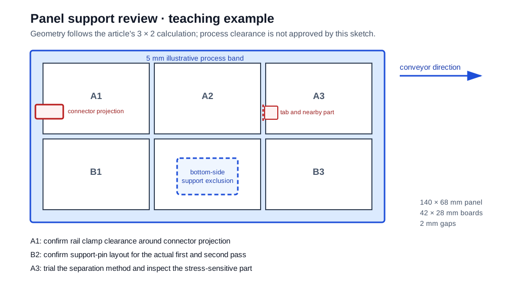
Use one panel revision across fabrication data, stencil, placement coordinates and assembly drawing. Mark the conveyor direction, panel datums and first-pass/second-pass underside condition. An overhanging connector or an underside component can make a mathematically valid array unusable in the intended fixture.
| Review item | Filled example observation | Evidence and owner needed | Example disposition |
|---|---|---|---|
| Drawing identity | Panel P-EX-01 rev A; six positions A1–A3 and B1–B3. Stencil and placement export revisions have not been matched. | Design owner supplies the release list; assembly engineer compares all exported revisions. | Hold until one revision set is identified. |
| Rail and clamp | The A1 connector projection crosses the assumed left clamp band. | Assembly engineer marks actual clamp contact and tests the proposed orientation or carrier with a representative board. | Hold; changing the opposite rail alone does not resolve the interference. |
| Bottom support | B2 has a tall underside part inside a proposed support-pin area. | Assembly engineer documents each pass state, support-pin map and first-print result. | Hold until the support method is trialled. |
| Separation stress | A3 has a stress-sensitive part near a proposed tab. | Design and manufacturing owners agree on tab position, tool/support method and post-separation inspection. | Hold pending a separation trial and product-specific acceptance criteria. |
| Final release | No trial-panel results or individual-board identity mapping are attached. | Project owner links position-level print, placement, reflow, separation and test records to the same panel revision. | Not approved; a completed sign-off requires named reviewers and dated evidence. |
This sheet is useful before an SMT assembly review: send the panel drawing, both-side component projection, intended delivery unit and separation responsibility. If the process route changes after a trial, revise the panel, stencil and coordinate package together; keep the old trial record attached to its original revision.
