Historical types · configuration reference
RF module assembly: configurations and test deliverables
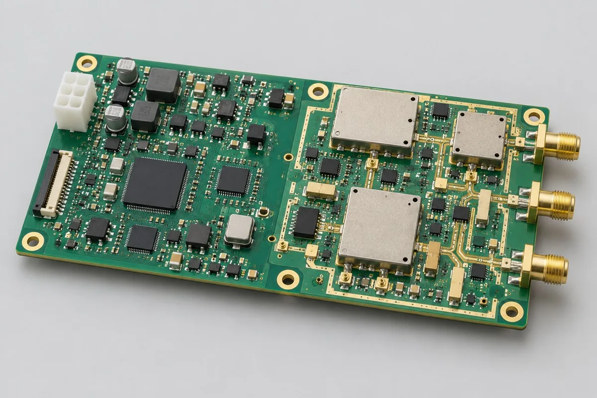
This illustrative multiband wireless transceiver and amplifier configuration supports engineering and procurement review. Power, interfaces, materials, firmware, and test conditions must be defined for the actual design. It is not evidence of a stocked model or a product developed or manufactured by KFPCBA. Approved files and order acceptance requirements govern.
Multiband RF assembly supports mobile-signal transceiver/amplifier procurement, with bands by order. Confirm amplifier units + splitting/filtering + controls, RF ports, USB/UART management, optional networking, and reference 4/6 layers with band-specific materials. Compare SMT → connectors/shields → firmware → band-link tests and link/switch/control/thermal acceptance costs. Separate modules + bands + calibration/revisions + curves from multicarrier/band/standard categories, without preset power, to clarify actual scope. RFQ reference:BOM · bare board · material supply
Reference specification and configuration options
| Options | Reference Configuration |
|---|---|
| Reference application | Medium-/low-power wireless transceivers; multicarrier/multiband/multistandard amplifier units |
| Power and Logic Domains | 12V reference input; multiple power domains |
| Functional Module | Mobile-signal transceiver/amplifier types; bands by order |
| Core Components/Architecture | Amplifier units + splitting/filtering + control references |
| Interface and Channels | RF ports; USB/UART management; optional networking |
| Board Layers and Material Options | 4/6-layer reference; RF materials designed by band |
| Component types | RF modules, QFN controls, matching parts, and shields |
| Assembly Route | SMT → connectors/shields → firmware → per-band link tests |
| Material Supply Scope | Specified modules/critical RF parts; locked filter/matching revisions |
| Firmware and Parameters | Bands/standards, gain tables, calibration, and management firmware |
| Test Focus | Per-band links, switching, control, and heat |
| Deliverables | Modules + band tables + calibration/revisions + test curves |
| Configuration Limits/Options | Multicarrier/band/standard categories; no preset power |
How much does multiband RF assembly cost, and what is included?
Filters, switches, modules, amplifiers, shielding, and cooling form costs. Band calibration/switching/heat tests vary with enabled combinations; one frequency does not cover everything. Low-/medium-power differences include cooling/matching, not parameter settings alone.
Quotation terms depend on the approved files, quantity, material supply, tests and delivery requirements.
Prepare a structured RFQ or use the short inquiry form.
| Cost Item | Scope for This Configuration | Billing frequency and work scope | Procurement Verification |
|---|---|---|---|
| Bare PCB and core components | Amplifier units + splitting/filtering + controls; 4/6-layer reference; band-specific materials | Price according to actual bare-board/component purchase quantities; authorize critical components and substitutions individually | Specified modules/critical RF parts; locked filter/matching revisions |
| Placement and Post-Assembly | SMT → connectors/shields → firmware → per-band link tests | Feeder/program setup per lot; assembly priced per board, joint, or process as agreed, with counting rules specified | RF modules, QFN controls, matching parts, and shields |
| Manufacturing Preparation | Review stencils, first articles, and support tooling against the actual assembly route | New stencils/carriers may be separate one-time charges; verify panelization, revision, and condition before reuse | Reduced quantities do not automatically eliminate first-article or feeder setup |
| Functional Support | Per-band links, switching, control, and heat | Itemize test-method/fixture/script setup; agree execution charges per board, channel, or test duration | Separate supporting development from execution records for each board |
| Software and Parameters | Bands/standards, gain tables, calibration, and management firmware | When firmware exists, distinguish file programming/verification from software development; omit programming without a firmware revision | Customer-approved files, parameters, and readback rules determine scope |
| Delivery and Change | Modules + bands + calibration/revisions + curves; multicarrier/band/standard types; no preset power | Price accessories, retesting, and revision changes by approved work items; do not prefill fixed rates | Check BOM, tooling, programs, and acceptance revisions before reorders |
How should shared and separate band paths be selected?
Shared broadband paths reduce parts but tighten filtering/linearity. Separate paths ease tuning but add area/heat cost. Fix bands, standards, and power tasks. Multicarrier names do not establish every network's compatibility.
| Comparison Metric | Current Conditions | Factors Influencing Procurement Decision |
|---|---|---|
| Manufacturing Delivery | SMT → connectors/shields → firmware → per-band link tests | Produce boards/assemblies per BOM and assembly drawings; this does not establish that every system function passes |
| Functional Acceptance | Per-band links, switching, control, and heat | Compare unit prices after defining test stimuli, limits, accessories, and records; review missing test inputs first |
| Configuration Options | RF ports; USB/UART management; optional networking; 4/6 layers; band-specific RF materials | Confirm circuit/program compatibility before reviewing assembly and test costs for interface, stackup, or component changes |
| Delivery Scope | Multicarrier/band/standard categories; no preset power | Complete-system accessories, application development, and project verification are not automatically included in board assembly |
How should multiband RF power be selected?
Define bands, ports, and use before amplification/filtering/thermal checks. Low-to-medium power changes need amplifier/cooling review, not gain-table edits or assumptions based on product categories.
- First list the mobile communication signal reception/transmission and amplification functions required for this order. Specify enabled bands by order and distinguish build-to-print manufacturing, configuration changes, and new feature development.
- Then freeze complete part numbers for the signal amplification unit + frequency splitting/filtering + control reference, RF ports, USB/UART management, optional network port, and the 4/6-layer reference. Select RF materials for the band design. Separate consigned and sourced items according to the specified modules/RF critical parts, with controlled filter and matching versions.
- Use the first article to verify SMT → connectors/shielding → firmware → per-band link testing, along with bands/standards, gain tables, calibration, and management firmware. If only firmware files are supplied, agree on programming verification first; review development separately.
- Convert per-band links, switching, control, and thermal behavior into acceptance items with stimuli, limits, and records. Define fixture ownership, testing of each board, and retesting after rework.
- Finally confirm the module + band table + calibration/version + test curves. Multicarrier/multiband/multistandard describes the product type; power is not specified in advance. Compare total prices using the same quantity, accessories, and test scope, then freeze the order version.
Applicable uses and situations requiring separate review
Mobile communication signal improvement in offices/homes and multiband signal amplification configurations.
A multiband description alone is insufficient for production without spectrum use conditions, power definitions, and a link budget. The system project must address lawful use, certification, and installation responsibilities for complete products using public wireless networks or regulated bands.
Assembly Challenges for This Product
Check reference designators and values for multiband switches, filters, and connectors as a complete set. Inspect RF paths before installing shielding, and fix connector torque and test calibration planes. Verify each enabled band separately; one frequency point does not represent the full configuration.
Structural, thermal, and configuration trade-offs
A shared broadband link reduces component count but increases filtering and linearity requirements. Separate band-specific links simplify debugging but increase board area, cost, and heat. Low-power and medium-power versions require different power amplifier and cooling configurations, not merely firmware settings.
Product-specific test matrix
| Test stage | Inspection/Functional Methods | Acceptance Record |
|---|---|---|
| Frequency Band Path | Check transmit/receive links individually for each band enabled by the order | Frequency band, measurement layout, and curves |
| Switch Control | Switch standards/paths and gain, and verify management readback | Status sheet and program version |
| Thermal and Structural | Retest at the specified duty cycle and shielding/cooling conditions | Power consumption, thermal test points, and mechanical revision |
Defect Handling and Acceptance
Address incorrect filters, wrong switching paths, poor connector solder joints, and misapplied calibration tables separately. Define bands, directions, and measurement reference planes for acceptance. Signal reception alone does not demonstrate consistent performance across the module.
Multiband transceiver PCBA: material supply and version control
Lock complete part numbers for RF modules and critical filters. Include calibration and interface definitions with customer-supplied RF accessories. Reassess links and regulatory conditions for substitutions; similar bands alone do not justify replacement.
Prototype and production planning
Confirm band combinations and cooling on engineering samples first. Freeze the calibration process for production, associate band tables with serial numbers, and perform link regression testing after shielding or mechanical changes.
Delivery Configuration
Module + band table + calibration/version + test curves. Multicarrier/multiband/multistandard describes the product type; power is not specified in advance.
Convert this configuration into a reviewable order
For multiband wireless transceiver module orders, verify the BOM, quantity, material supply, and conditions below. Provide the pick-and-place file/CPL, DNP list, and assembly drawing for this board's SMT process. For contracted programming, provide files, programming rules, and verification requirements for bands/standards, gain tables, calibration, and management firmware. Review costs separately for materials, SMT → connectors/shielding → firmware → per-band link testing, and required stencil/loading, support carriers, and test resources. Reapprove versions after documentation changes, and agree on delivery milestones once material readiness and scheduling are confirmed.
| Required project inputs | Engineering Decisions Affected | Records/delivery as agreed in the order |
|---|---|---|
| Band/standard combination | Provide the actual enabled bands, standards, ports, and transmit/receive acceptance items. A product-category name does not establish compatibility across bands or standards. | Retain RF records, firmware, and calibration parameters separately for each combination. |
| Amplifier Link Support | Specify whether antennas, attenuators, heatsinks, and enclosures are delivered with the module. | Archive the test reference plane and actual combination. Confirm output power limits under this order's test conditions. |
Multiband RF module assembly FAQ
How much does multiband RF assembly cost, and what is included?
Itemize band-specific components, shielding, firmware, calibration, and per-band link tests. Confirm the files, quantities, material responsibilities, test records, delivery destination, currency, taxes, shipping, and trade terms before comparing totals. Review the quotation scope.
Are multiband module quotations priced by band?
Materials may be shared, but each enabled band requires its own link and calibration work. Quotations should state the assembly version, test frequencies, and record scope so a low price does not cover only one link.
How can support for a specified carrier be determined?
Check the relevant bands, standards, interfaces, and actual system validation. A reference configuration does not establish support for every network. Use an explicit band table and version records for each order.
Should multiband RF amplification units be tested before and after shielding?
Check components and RF paths before fitting the shield, then compare links and thermal behavior afterward. Retain results for each enabled band. Shield installation must not replace inspection of the original solder joints.
Why must multiband module substitutions be checked as a complete set?
Switches, filters, and matching components jointly determine the path. Equal component values do not guarantee equal frequency behavior. Match the new BOM to the band table and firmware. Substitution validation goes beyond routine incoming visual inspection.
How should band-path testing be included in purchasing acceptance for multiband RF module assembly?
The reference method for this configuration checks transmit/receive links individually for each band enabled by the order. Records should include bands, measurement setup, and curves. Provide test inputs, applicable configurations, and acceptance limits with the RFQ, then agree on the scope of first-article verification and testing of each board. Price test preparation separately from each execution. If limits are missing, the method can be reviewed first, but completing a procedure cannot be described as meeting performance requirements.
How should switching control testing be included in purchasing acceptance for multiband RF module assembly?
The reference method for this configuration switches standards/paths and gain and verifies management readback. Records should include the state table and firmware version. Provide test inputs, applicable configurations, and acceptance limits with the RFQ, then agree on the scope of first-article verification and testing of each board. Price test preparation separately from each execution. If limits are missing, the method can be reviewed first, but completing a procedure cannot be described as meeting performance requirements.
How should thermal and mechanical testing be included in purchasing acceptance for multiband RF module assembly?
The reference method for this configuration retests at the specified duty cycle and shielding/cooling conditions. Records should include power consumption, thermal measurement points, and mechanical revision. Provide test inputs, applicable configurations, and acceptance limits with the RFQ, then agree on the scope of first-article verification and testing of each board. Price test preparation separately from each execution. If limits are missing, the method can be reviewed first, but completing a procedure cannot be described as meeting performance requirements.
How are programming and development priced separately when the customer provides firmware for multiband RF module assembly?
Controlled items for this configuration are bands/standards, gain tables, calibration, and management firmware. Programming, parameter loading, and readback verification using customer-approved files are manufacturing operations. New logic, interface adaptation, and algorithm changes require development review. Quote preparation, programming of each board, verification, and failure handling separately. Including programming does not imply application development is included.
Must first-article, stencil, and loading charges be recalculated for repeat multiband RF module assembly orders?
The process for this configuration is SMT → connectors/shielding → firmware → per-band link testing. For SMT, verify the stencil and panelization; for through-hole or later-installed parts, verify support and assembly methods. Agree on loading and first-article work for this batch. Reuse existing tooling only when its version, position, and condition match. After changing components or interfaces in the RF module, QFN controller, matching components, or shielding structure, first review effects on tooling and per-band links, switching, control, and thermal behavior, then confirm repeat charges.
How should total prices be compared when critical parts are consigned and the remaining materials are sourced for multiband RF module assembly?
Create a purchasing responsibility matrix using this page's specified modules/RF critical parts and controlled filter/matching versions. Confirm complete part numbers, quantities, packaging, and excess-material rules with the materials. Consignment only changes purchasing responsibility. SMT → connectors/shielding → firmware → per-band link testing, along with per-band links, switching, control, and thermal checks, remain actual work. Approve the effects of shortages, substitutions, or lot changes first. Do not directly compare consigned-material unit prices with complete assembly prices that include materials.
Which tests should be repeated after rework or supplemental multiband RF module assembly orders?
Select retests based on the effects of the change. Original acceptance items for this configuration are per-band links, switching, control, and thermal behavior; shipment records comprise the module + band table + calibration/version + test curves. When rework affects power, interfaces, critical analog circuitry, or software versions, check related tests rather than only the repaired solder joint. Align supplemental orders with the original BOM, parameters, and test resources. Agree on retest charges based on approved items and actual quantities tested, without assuming free service or a fixed turnaround.
Compare Other Products in This Category
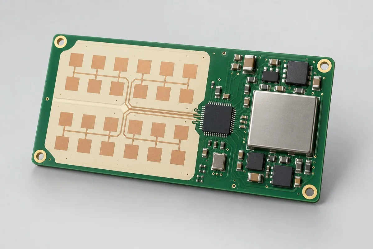
- Millimeter-Wave Presence Detection Board: Radar antenna and housing impact.
- RF Transceiver Interface Board: RF link and shield connection.
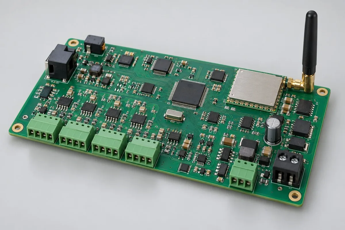
- Wireless Measurement Gateway Board: Module RF and industrial acquisition on same board.
Return to high-frequency PCB assembly configuration comparison · Component Supply and Procurement · Testing and Delivery Scope
Material and Process Reference
- Engineering reference | SMT packages and assembly methods: pads, stencils, and thermal processes: a package/assembly method index only; not evidence that the product configurations on this page are models produced by KFPCBA
- Engineering reference | Moisture-sensitive component management: MSL, floor life, and reflow conditions: a basis for moisture-sensitive component management methods only; not evidence of KFPCBA equipment, qualifications, or order scope