Engineering Reference Configuration
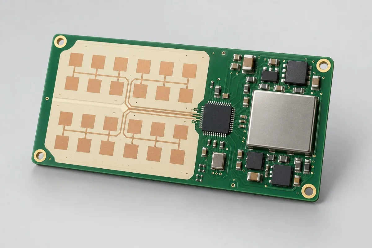
Millimeter-wave radar PCB assembly: assembly configuration and test deliverables
The following adjustable engineering configurations support material, functional, and process review; they are not stocked models or commitments to current production-line capabilities. Approved fabrication documentation and order acceptance requirements govern.
Millimeter-wave radar PCB assembly supports contract manufacturing and procurement review for presence/motion sensing. First confirm an optional TI IWR6843 design or project-approved radar module, UART target information, optional CAN/debug interfaces, and 4/6-layer designs using FR-4 or RF materials according to antenna design. Then compare SMT → hidden-joint verification → RF inspection → parameter programming scope and acceptance costs for startup, static/moving scenarios, interfaces, and enclosure comparisons. This page separates sensing board + configuration file + scenario records from separate verification of unenclosed boards and assemblies with specified enclosures, helping determine whether quotations cover the actual application. Quotation documentation reference:BOM · bare board · material supply
Reference specification and configuration options
| Options | Reference Configuration |
|---|---|
| Power and Logic Domains | 5V input; internal multi-power domain |
| Functional Module | Millimeter-wave presence/motion sensing |
| Core Components/Architecture | Optional TI IWR6843 design or project-approved radar module |
| Interface and Channels | UART target information; optional CAN/debug interfaces |
| Board Layers and Material Options | 4/6-layer designs; FR-4 or RF materials according to antenna design |
| Component packages | Radar BGA or module, clock, power supply, and onboard antenna |
| Assembly Route | SMT → hidden-joint verification → RF inspection → parameter programming |
| Material Supply Scope | Radar component/module revisions locked; antenna geometry is not a material substitution |
| Firmware and Parameters | Separate radar parameters, application firmware, and configuration files |
| Test Focus | Startup, static/moving scenarios, interfaces, and enclosure comparisons |
| Deliverables | Sensing board + configuration file + scenario-test records |
| Configuration Limits/Options | Verify unenclosed boards and assemblies with specified enclosures separately |
How much does millimeter-wave radar PCB assembly cost, and what is included?
Radar components/modules, board materials, reference clocks, and power components drive material differences. Direct radar BGA assembly differs from module installation. Itemize startup, target scenarios, parameter programming, and specified-enclosure tests; algorithm development and enclosure design are separate. BGA counts alone cannot compare sensing-board quotations.
Quotation terms depend on the approved files, quantity, material supply, tests and delivery requirements.
Prepare a structured RFQ or use the short inquiry form.
| Cost Item | Scope for This Configuration | Billing frequency and work scope | Procurement Verification |
|---|---|---|---|
| Bare PCB and core components | Optional TI IWR6843 design or project-approved radar module; 4/6-layer designs; FR-4 or RF materials according to antenna design | Price according to actual bare-board/component purchase quantities; authorize critical components and substitutions individually | Radar component/module revisions locked; antenna geometry is not a material substitution |
| Placement and secondary assembly | SMT → hidden-joint verification → RF inspection → parameter programming | Feeder/program setup per lot; assembly priced per board, joint, or process as agreed, with counting rules specified | Radar BGA or module, clock, power supply, and onboard antenna |
| Manufacturing Preparation | Review stencils, first articles, and support tooling against the actual assembly route | New stencils/carriers may be separate one-time charges; verify panelization, revision, and condition before reuse | Reduced quantities do not automatically eliminate first-article or feeder setup |
| Test resources and execution | Startup, static/moving scenarios, interfaces, and enclosure comparisons | Itemize test-method/fixture/script setup; agree execution charges per board, channel, or test duration | Separate supporting development from execution records for each board |
| Software and Parameters | Separate radar parameters, application firmware, and configuration files | When firmware exists, distinguish file programming/verification from software development; omit programming without a firmware revision | Customer-approved files, parameters, and readback rules determine scope |
| Delivery and Change | Sensing board + configuration file + scenario records; verify unenclosed boards and assemblies with specified enclosures separately | Price accessories, retesting, and revision changes by approved work items; do not prefill fixed rates | Check BOM, tooling, programs, and acceptance revisions before reorders |
Is a millimeter-wave radar chip design or module design preferable?
Modules can reduce RF/software adaptation but are constrained by module interfaces, dimensions, and licensing. Chip-on-board designs offer flexibility while requiring antenna, power, and scenario verification. Select by development resources and installation structures, beyond module unit prices.
| Comparison Metric | Current Conditions | Factors Influencing Procurement Decision |
|---|---|---|
| Manufacturing Delivery | SMT → hidden-joint verification → RF inspection → parameter programming | Produce boards/assemblies per BOM and assembly drawings; this does not establish that every system function passes |
| Functional Acceptance | Startup, static/moving scenarios, interfaces, and enclosure comparisons | Compare unit prices after defining test stimuli, limits, accessories, and records; review missing test inputs first |
| Configuration Options | UART target information; optional CAN/debug interfaces; 4/6-layer designs; FR-4 or RF materials according to antenna design | Confirm circuit/program compatibility before reviewing assembly and test costs for interface, stackup, or component changes |
| Delivery Scope | Verify unenclosed boards and assemblies with specified enclosures separately | Complete-system accessories, application development, and project verification are not automatically included in board assembly |
Should millimeter-wave radar PCBs use FR-4 or RF materials?
Determine materials from antenna structures, frequency bands, and supplier design requirements; the radar designation alone cannot select materials. Enclosures, metal, and coatings around antennas affect overall scenarios. Align acceptance conditions for unenclosed boards and enclosed assemblies when comparing quotations.
- First list required millimeter-wave presence/motion sensing, distinguishing build-to-print manufacturing, configuration adjustments, and new-function development.
- Then freeze complete part numbers for the optional TI IWR6843 design or project-approved radar module, UART target information, optional CAN/debug interfaces, and 4/6-layer designs using FR-4 or RF materials according to antenna design. Separate customer-supplied and sourced materials with radar component/module revisions locked; antenna geometry is not a material substitution.
- Use first articles to check SMT → hidden-joint verification → RF inspection → parameter programming and separate radar parameters, application firmware, and configuration files. If only program files are supplied, agree programming verification first; development requires separate review.
- Convert startup, static/moving scenarios, interfaces, and enclosure comparisons into acceptance items with stimuli, limits, and records; specify fixture ownership, per-board execution, and post-repair retesting.
- Finally confirm sensing board + configuration file + scenario records and separate verification of unenclosed boards and assemblies with specified enclosures. Compare totals using identical quantities, accessories, and test scope, then freeze the order revision.
Applicable uses and situations requiring separate review
Area occupancy sensing, equipment-motion detection, human-machine interaction sensing.
Protective systems requiring defined safety ratings, medical vital-sign conclusions, or outdoor long-range speed measurement cannot directly adopt presence-sensing reference configurations. Shielding cans and metal enclosures affect antennas; installation environments require verification.
Assembly Challenges for This Product
Keep uncontrolled solder, conductive residue, and later-installed metal parts away from antenna areas. Establish separate power-up and assembly checks for radar packages and reference clocks. Depaneling, fastening, and coatings must not change surrounding antenna dielectrics; perform separate scenario tests after installing enclosures.
Structural, thermal, and configuration trade-offs
Onboard antennas are compact but depend on materials, structures, and production consistency. Established modules reduce RF design work but constrain height, interfaces, and algorithm licensing according to suppliers. Higher transmit power does not directly compensate for obstructions.
Configuration-specific test matrix
| node | Inspection/Functional Methods | Acceptance Record |
|---|---|---|
| Startup/Configuration | Confirm power supply, device identification, and parameter loading | Version and Boot Logs |
| Scenario sensing | Set occupied, unoccupied, and moving-target scenarios at specified distances/orientations | False-positive/missed-detection samples and scenario conditions; project-defined thresholds |
| Structural Impact | Compare the same assembled board without an enclosure and inside the specified enclosure | Housing version and result differences |
Defect Handling and Acceptance
Separate soldering defects from antenna/algorithm issues. For startup failures, check power and package connections first. Direction-specific missed detections require structural, antenna, and parameter checks. Acceptance matrices must record targets, positioning, and environments.
Millimeter-wave sensing PCB assembly: material supply and revision management
Do not substitute radar modules by frequency band alone; interfaces, algorithm outputs, and regional compliance must match. Lock customer-supplied enclosure materials and surface coatings. Pre-delivery enclosed tests and board-level inspections are priced separately.
Prototyping vs. Production Differences
Samples establish sensing areas and parameters. Production freezes algorithms, enclosures, and mounting positions, using stable scenario fixtures to check responses. The complete-system responsible party arranges regulatory tests and identifies the testing organization; contract manufacturing does not automatically confer certification.
Delivery Configuration
Sensing board + configuration file + scenario records. Verify unenclosed boards and assemblies with specified enclosures separately.
Convert this configuration into a reviewable order
For millimeter-wave presence-sensing board orders, check BOM, quantity, material supply, and the conditions below. Add pick-and-place files, DNP lists, and assembly drawings for SMT. For programming, provide separate radar-parameter, application-firmware, and configuration files with programming rules and verification requirements. Review costs separately for materials, SMT → hidden-joint verification → RF inspection → parameter programming, required stencils/feeder setup, support carriers, and test resources. Documentation changes require renewed revision approval; agree delivery milestones after material readiness and scheduling confirmation.
| Project inputs required for review | Engineering decisions | Records/delivery as agreed in the order |
|---|---|---|
| Radar Operating Environment | Provide mounting height, orientation, enclosure materials, and stationary/moving-target requirements to determine test scenarios and firmware parameters. | Record scenarios, distances, parameter revisions, and raw detection results; module-rated distances do not guarantee complete-system performance. |
| Antenna/Module Scope | Lock chip designs or module part numbers; specify soldering in antenna areas and required shielding cans. | Link material and assembly revisions to radar tests; module certification does not replace complete-system compliance. |
Millimeter-wave radar PCB assembly FAQs
How much does millimeter-wave radar PCB assembly cost, and what is included?
Count standard placement and QFN/BGA points separately, then add setup, subsequent installation, and inspection fees. A project-specific quotation requires review of the available files, quantity, materials, requested tests, delivery destination, taxes, shipping, and trade terms. Agree the billing unit and currency in the quotation; list bare PCBs, BOM components, and testing separately. No current unit prices are published here; request an itemized quotation for the approved scope.Review quotation inputs and scope.
Is a millimeter-wave radar chip design or module design preferable?
Modules can reduce RF/software adaptation but are constrained by module interfaces, dimensions, and licensing. Chip-on-board designs offer flexibility while requiring antenna, power, and scenario verification. Select by development resources and installation structures, beyond module unit prices.
Should millimeter-wave radar PCBs use FR-4 or RF materials?
Determine materials from antenna structures, frequency bands, and supplier design requirements; the radar designation alone cannot select materials. Enclosures, metal, and coatings around antennas affect overall scenarios. Align acceptance conditions for unenclosed boards and enclosed assemblies when comparing quotations.
Does millimeter-wave radar PCB assembly pricing include sensing algorithms?
Separate parameter loading, customer-firmware programming, and algorithm development. Execute scenario tests with specified stationary/moving targets and installation conditions. Powered operation does not establish completion of every target-recognition function.
Does changing a radar module enclosure require retesting?
Compare target and interface results before and after enclosure installation. Enclosure materials, thickness, and surrounding metal alter antenna environments; passing unenclosed-board tests cannot replace final-installation tests.
Must actual installation scenarios be provided for radar PCB assembly testing?
Provide mounting directions, specified enclosures, and target scenarios, distinguishing stationary, moving, and interface tests. Scenario setup differs from parameter programming; radar part numbers alone cannot define sensing acceptance.
Can structures around antennas be freely changed after supplying radar modules?
Completed assembly does not authorize arbitrary structural changes. Metal, coatings, and fastening alter antenna environments. After structural changes, repeat scenario comparisons under identical conditions while retaining module and program revisions.
How should startup/configuration testing be included in millimeter-wave radar procurement acceptance?
The reference method confirms power supply, device identification, and parameter loading. Records include revisions and startup logs. Supply test inputs, applicable configurations, and acceptance limits with the inquiry, then agree first-article verification and per-board execution scope. Price test-resource setup separately from each execution. Methods can be reviewed before limits are available, but completing an operation does not establish specification compliance.
How should scenario-sensing testing be included in millimeter-wave radar procurement acceptance?
The reference method sets occupied, unoccupied, and moving-target scenarios at specified distances/orientations. Records include false-positive/missed-detection samples and scenario conditions, with project-defined thresholds. Supply test inputs, applicable configurations, and acceptance limits with the inquiry, then agree first-article verification and per-board execution scope. Price test-resource setup separately from each execution. Methods can be reviewed before limits are available, but completing an operation does not establish specification compliance.
How should structural-impact testing be included in millimeter-wave radar procurement acceptance?
The reference method compares the same board unenclosed and inside a specified enclosure. Records include enclosure revisions and result differences. Supply test inputs, applicable configurations, and acceptance limits with the inquiry, then agree first-article verification and per-board execution scope. Price test-resource setup separately from each execution. Methods can be reviewed before limits are available, but completing an operation does not establish specification compliance.
How are programming and development priced separately when customers supply millimeter-wave radar software?
Controlled content separates radar parameters, application firmware, and configuration files. Programming customer-approved files, loading parameters, and verifying readback are manufacturing operations; new logic, interface adaptation, or algorithm changes require development review. Separately price resource setup, per-board programming, verification, and failure handling. Programming included does not imply application development included.
Is millimeter-wave radar BGA hidden-joint inspection priced per component or per board?
This page specifies radar BGAs/modules, clocks, power supplies, and onboard antennas. List actual BGA part numbers, quantities, and joint-inspection scope before agreeing charges per component, board, or inspection time. Define methods, inspection coverage, image retention, and post-rework reinspection. Startup, static/moving scenarios, interfaces, and enclosure comparisons require independent confirmation. Determine inspection dimensions, coverage, and equipment methods with actual packages; the BGA designation alone does not establish them.
How should total millimeter-wave radar assembly costs be compared when critical components are customer-supplied and others sourced?
Create a procurement-responsibility table with radar component/module revisions locked; antenna geometry is not a material substitution. Confirm complete part numbers, quantities, packaging, and remaining-material rules with deliveries. Customer supply changes only procurement boundaries; SMT → hidden-joint verification → RF inspection → parameter programming and startup, static/moving scenarios, interfaces, and enclosure comparisons remain actual work. Approve shortage, substitution, or lot-change impacts first; do not directly compare consigned assembly unit prices with material-inclusive assembly totals.
What requires retesting after millimeter-wave radar repairs or repeat orders?
Select retests by change impact. Original acceptance covers startup, static/moving scenarios, interfaces, and enclosure comparisons; shipping records include sensing board + configuration file + scenario records. Repairs affecting power, interfaces, critical analog circuits, or software revisions require related tests, beyond repaired joints. Repeat orders must align with original BOMs, parameters, and test resources. Agree retest charges by approved items and actual quantities; do not assume free service or fixed turnaround.
Compare Other Products in This Category
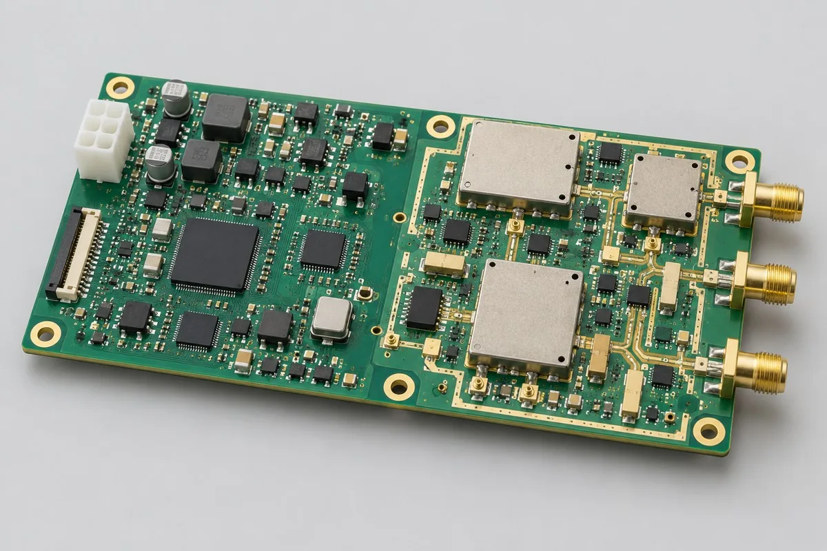
- RF Transceiver Interface Board: RF link and shield connection.
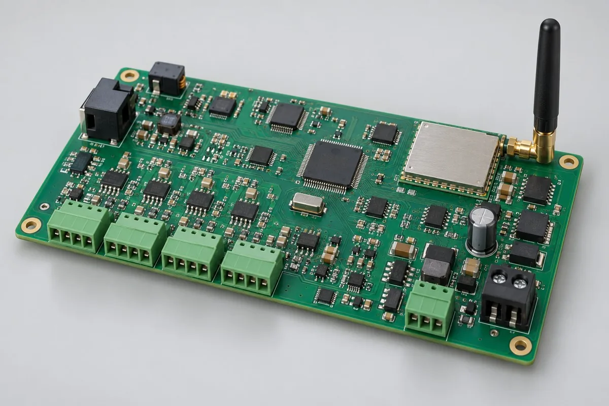
- Wireless Measurement Gateway Board: Module RF and industrial acquisition on same board.
- Multi-band wireless signal transceiver module: Engineering reference configuration; frequency bands and interfaces require project-specific definition.
Return to high-frequency PCB assembly configuration comparison · Component Supply and Procurement · Testing and Delivery Scope
Material and Process Reference
- Engineering reference | SMT packages and assembly methods: pads, stencils, and thermal processes: a package/assembly method index only; not evidence that the product configurations on this page are models produced by KFPCBA
- Engineering reference | Moisture-sensitive component management: MSL, floor life, and reflow conditions: a basis for moisture-sensitive component management methods only; not evidence of KFPCBA equipment, qualifications, or order scope
- Engineering reference | IWR6843 component reference: selection conditions and board-level verification: checks only the 60–64GHz candidate component band/interfaces; does not establish complete board range, accuracy, or finished product qualification
To request an assembly review, send an RFQ with the quantity, BOM revision, assembly files, material-supply responsibilities and required test records. Agree any design or test work separately.