Engineering Selection Reference
Camera mainboard PCBs: ten-layer two-step staggered-via HDI fabrication review
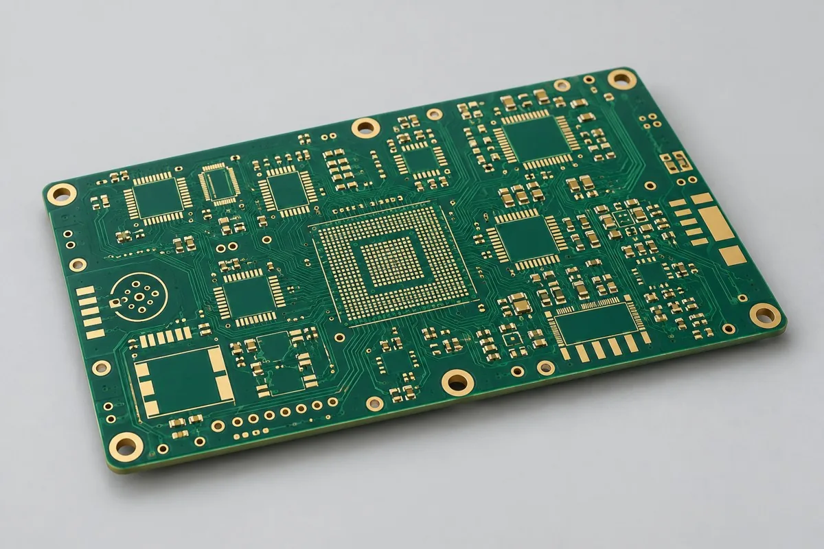
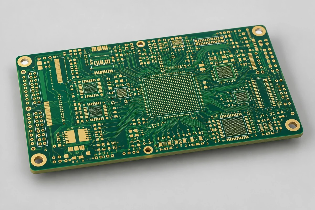
Review ten-layer two-step staggered-via HDI fabrication against current drawings. Bare camera computing boards require 2-6-2 stage-specific drill tables and processor pads. Review staggered-via space, outer copper weight, and fine-trace candidates together. Deliver build-up sequences, via filling/planarization, and agreed microsections across both steps. Reference combinations are not factory limits.
First define bare PCB prototyping or production scope for camera mainboard PCBs. Provide Gerber data, drill files, board outline, and layer stackup, materials and processes, quantity, and fabrication acceptance requirements. Two-step staggered vias support denser fanout without defaulting to stacked vias at the expense of verifiability
Why choose this structure for two-step camera HDI boards?
Consider ten-layer 2-6-2 two-step staggered-via HDI when dense camera/computing mainboards need two consecutive outer-layer fanout stages. Staggered microvias separate the two build-up connections. Procurement must define each step's via layer pairs, fanout space, and connection verification rather than specifying only two-step HDI.
How should ten-layer two-step HDI camera computing prototyping costs be broken down?
Break costs into two build-up stages, stage-specific laser/buried vias, staggered-via coordinate control, copper-filled pad surfaces, and critical interconnect inspection. Review the 0.075mm fine-trace candidate with 25µm outer copper separately; do not combine it with the 35µm primary option in one quote. Compare primary and candidate options separately to distinguish microvia costs from fine-trace and planarization costs.
Quotation terms depend on the approved files, quantity, material supply, tests and delivery requirements.
Prepare a structured RFQ or use the short inquiry form.
Enter the following items in one itemized quotation: specify cost units and tax/shipping basis, with separate columns for first orders and same-revision repeat orders. The table is a procurement breakdown method, not a ready-made price list; reference specifications require approval against current fabrication drawings.
| Quotation items and pricing boundaries | Configuration inputs to confirm | Repeat orders and revision changes |
|---|---|---|
| Materials/fabrication, quoted per batch or accepted board | Isola 370HR FR4 (reference material system); 10-layer 2-step HDI, 2-6-2; inner base copper 18µm; primary outer base copper 18µm/finished 35µm; fine-trace candidate finished 25µm requires separate filling/planarization review | Recurs on repeat orders; material, layer-order, or copper-weight changes require requotation |
| Holes and forming, per approved hole table | L1-L2 and L2-L3 staggered Ø0.10mm microvias, symmetric on bottom; L3-L8 Ø0.20mm buried vias | Repeat orders use the same fabrication revision; review processes before changing two-step staggered-via relationships |
| Surface finish/packaging, noting areas and batches | ENIG; specify copper-filled and planarized via-in-pad scope pad by pad | Incurred by actual batch; confirm packaging, storage conditions, and surface-finish substitutions separately |
| Engineering/tooling preparation, identifying one-time or per-batch charges | Two-step staggered-via relationships: submit drill tables for each 2-6-2 lamination stage, via offset distances, and pad overlap locations. | Verify file revisions, ownership, and storage condition before reusing old tooling; do not assume reuse is free |
| Structural/special inspections, identifying coupons, hole groups, or samples | Agree on microsections covering both microvia steps and buried vias, not only the outermost step. Retain via structure approvals, filling requirements, and pad flatness inspection results. | List initial prototype validation and per-batch sampling separately; quote per-board requirements separately rather than assuming everything is completed once |
| Delivery scope, reports, and accepted quantity | Two-step HDI bare PCBs, build-up sequence/staggered-via coordinates, material lots, interconnect coupons, and microsection reports; include target-net TDR by agreement. | Retain revision links and batch records on repeat orders; list component assembly, firmware, and complete-unit testing separately |
How do two-step staggered and stacked vias differ on camera computing boards?
Staggered vias offset the two microvia steps laterally, requiring routing space. Stacked vias reduce lateral space but need different interface and filling verification. This product defaults to two-step staggered vias without automatically including stacked vias. Assess processor pads and space before comparing manufacturable structures and interconnect verification; area savings alone are insufficient.
| Comparison Dimension | Camera computing board HDI PCB fabrication | Six-layer single-build-up HDI PCB prototyping |
|---|---|---|
| Material and Grade | Isola 370HR FR4 (reference material system) | Isola 370HR FR4 |
| Layer Count and Structure | 10-layer 2-stage HDI, 2-6-2 | 6-layer single-build-up HDI, 1-4-1 |
| Hole Structure and Dimensions | L1-L2 and L2-L3 staggered Ø0.10mm microvias, symmetric on bottom; L3-L8 Ø0.20mm buried vias | Ø0.10mm microvias on both sides; L2-L5 Ø0.20mm buried vias; reduced mechanical through-hole space |
| Application | Compact camera-processing mainboards; high-I/O image-processing interfaces | Small sensor interfaces; compact module control bare boards |
Can camera HDI combine 0.075mm traces and 35µm copper?
The primary option is 0.10/0.10mm with 35µm finished outer copper; 0.075/0.075mm with 25µm outer copper is only a candidate. Finer traces require review of lateral etching, copper reduction after filled-via planarization, and actual cross-sections. Choose the primary or candidate option rather than combining minimum and maximum values from separate rows.
| Decision Sequence | Required project inputs | Agreed records and deliverables |
|---|---|---|
| 1. Define application and scope | Submit drill tables for each 2-6-2 lamination stage, via offset distances, and pad overlap locations. | Agree on microsections covering both microvia steps and buried vias, not only the outermost step. |
| 2. Confirm structural requirements | Provide processor packages and reference pad drawings, specifying whether filling/copper capping is required at pad surfaces. | Retain via structure approvals, filling requirements, and pad flatness inspection results. |
| 3. Align nets with fabrication targets | 100Ω differential camera link target; critical via interconnect coupons/TDR | Provide target nets, layer pairs, and verification scope; review with staggered L1-L2 and L2-L3 Ø0.10mm microvias, symmetric bottom side, and L3-L8 Ø0.20mm buried vias |
| 4. Confirm quotation and release revision | Isola 370HR FR4 (reference material system); 1.20mm reference target; ENIG; specify copper-filled and planarized via-in-pad scope pad by pad | Request quotations using material/pattern/inspection lists at the same revision; list unapproved substitutions as separate alternatives rather than including them in the baseline quotation |
Camera Two-Stage HDI Board Manufacturing Specifications
| Specification Items | Reference configuration or target |
|---|---|
| Material and Grade | Isola 370HR FR4 (reference material system) |
| Layer Count and Structure | 10-layer 2-stage HDI, 2-6-2 |
| Total Board Thickness | 1.20mm reference target |
| Dielectric thickness and interlayer relationship | Target dielectric thickness 0.060mm for each build-up stage |
| Base Copper and Finished Copper | Inner base copper 18µm; primary outer base copper 18µm/finished 35µm; fine-trace candidate finished 25µm requires separate filling/planarization review |
| Hole Structure and Dimensions | L1-L2 and L2-L3 staggered Ø0.10mm microvias, symmetric on bottom; L3-L8 Ø0.20mm buried vias |
| Trace Width and Spacing | Primary 0.10/0.10mm (35µm finished outer copper); 0.075/0.075mm only as a 25µm outer-copper candidate, with separate combination and etch compensation review |
| Impedance Target and Measurement Methods | 100Ω differential camera link target; critical via interconnect coupons/TDR |
| Surface Finish | ENIG; specify copper-filled and planarized via-in-pad scope pad by pad |
| Application | Compact camera-processing mainboards; high-I/O image-processing interfaces |
| Deliverables | Two-step HDI bare PCBs, build-up sequence/staggered-via coordinates, material lots, interconnect coupons, and microsection reports; include target-net TDR by agreement. |
Two-step camera HDI board layer order and via structures
The following shows functional layer order/material structure for this reference configuration, not a production stackup drawing; do not infer thickness from graphic proportions. Match copper-layer numbering to via layer pairs item by item in approved fabrication files.
| Top to Bottom | Layer Responsibilities/Structure |
|---|---|
| L1 | Components / first build-up fanout |
| L2 | Second build-up fanout plus local ground |
| L3 | Core Signal |
| L4 | ground |
| L5 | Power A |
| L6 | Power B |
| L7 | ground |
| L8 | Core Signal |
| L9 | Second build-up fanout plus local ground |
| L10 | Components / first build-up fanout |
Via structure: staggered L1-L2 and L2-L3 Ø0.10mm microvias, symmetric bottom side; L3-L8 Ø0.20mm buried vias
Tradeoffs between staggered-via lateral space and changing to stacked vias
Two-step HDI increases connection flexibility and lamination/microvia costs. Staggered vias need lateral space; space-constrained projects may separately review stacked vias. Stacked vias are not the default, and microvia step count does not guarantee feasibility at every BGA pitch.
Two-step alignment, via-fill flatness, and fine-trace copper weight: fabrication inspection
Number via layer pairs, capture pads, and keepouts separately for both build-up stages. Evaluate 0.060mm dielectric thickness with 0.10mm vias as one combination. First articles focus on short staggered-via connections and inner-layer alignment, with copper-filled pad acceptance defined separately for assembly. The primary option is 0.10/0.10mm with 35µm finished outer copper. The denser 0.075/0.075mm is only a 25µm finished-copper candidate, not a proven simultaneous combination transferred from third-party fine-trace examples. Review etch compensation, lateral etching, planarization/copper reduction after microvia filling, and finished cross-sections before retaining fine traces or widening them.
Daisy chains across both steps and thermally stressed interconnects: acceptance items
Use daisy chains/microsections spanning both steps to inspect via interfaces and pad depressions. Measure connection resistance and differential TDR before and after thermal stress by agreement. Define allowable changes and sample quantities in advance rather than relying only on X-ray images.
Camera Two-Stage HDI Board Delivery Scope
Applications: compact camera computing mainboards; high-I/O image-processing interfaces.
Two-step HDI bare PCBs, build-up sequence/staggered-via coordinates, material lots, interconnect coupons, and microsection reports; include target-net TDR by agreement.
Drill tables for each lamination stage and processor pads: RFQ inputs
Submit drill tables for each lamination stage and processor pads to turn tabled design targets into inspectable fabrication drawings. The inputs below define pattern, material, or structural inspection scope. Freeze the quote revision with approved drawings.
| Project inputs required for review | Engineering decisions | Records/delivery as agreed in the order |
|---|---|---|
| Two-step staggered-via relationships | Submit drill tables for each 2-6-2 lamination stage, via offset distances, and pad overlap locations. | Agree on microsections covering both microvia steps and buried vias, not only the outermost step. |
| Camera processor fanout | Provide processor packages and reference pad drawings, specifying whether filling/copper capping is required at pad surfaces. | Retain via structure approvals, filling requirements, and pad flatness inspection results. |
Camera computing HDI PCB fabrication: pricing, selection, and purchasing FAQ
How should ten-layer two-step HDI camera computing prototyping costs be broken down?
A project-specific quotation requires review of the available files, quantity, materials, requested tests, delivery destination, taxes, shipping, and trade terms. This is not a complete finished-product quotation. Base fabrication/sample pricing, special processes, and inspections must not be billed twice. No current unit prices are published here; request an itemized quotation for the approved scope.Review quotation inputs and scope.
How do two-step staggered and stacked vias differ on camera computing boards?
Two-step staggered vias offset the microvia levels laterally and require space. Stacked vias reduce lateral space but need separately defined filling and interface verification. This product defaults to staggered vias. Select by processor pads and available space rather than automatically changing to stacked vias based on area alone. Review the comparison
Can camera HDI combine 0.075mm traces and 35µm copper?
The primary option is 0.10/0.10mm with 35µm outer copper; 0.075/0.075mm with 25µm is only a candidate. Finer traces need lateral etching, post-fill planarization/copper reduction, and cross-section review. Do not combine extremes from the two options. Review the comparison
Does every camera board require two-step HDI?
No. Use it only when small packages and high-I/O breakout actually require both steps. Compare costs and verification for camera interfaces achievable with through-holes or single-step HDI first. The camera application name does not determine HDI step count.
Can a two-step board move to production after passing X-ray?
Images do not replace microsections spanning both steps and interconnect resistance verification before and after specified thermal stress. First articles must cover both microvia steps and buried vias, followed by frozen materials, build-up, and pad-surface routes.
Do camera HDI quotes include via filling in pads?
Specify pad by pad which microvias lie in component pads and what copper filling and planarization they require. Two-step HDI does not imply every via is filled flat or camera component soldering and functional testing are included.
Can sampling only outermost-step microsections reduce two-step camera HDI testing costs?
It reduces coverage and cannot establish acceptance of both microvia steps and central-core buried vias. Quotes must identify representative vias for every lamination stage, staggered relationships, and via-in-pad requirements. Compare inspection plans covering the same structures. Outermost-step results cannot release inner steps.
How do per-board and per-panel camera computing HDI PCB fabrication quotes convert?
Arrange inspection structures by stage for 2-6-2 microvias, buried vias, and via-in-pad. Do not raise utilization while retaining only outermost-step microsection samples. Quotes state finished boards per panel, purchased panels, and individual-board/panel delivery state. Divide actual panel fabrication cost by accepted finished boards for per-board cost. List setup, special inspection, and packaging separately; theoretical utilization does not guarantee yield.
How should one-time first-order and repeat-order costs be separated for camera computing HDI PCB fabrication?
First confirm two-step staggered-via relationships and camera computing fanout files, identifying whether related engineering, tooling, or test setup is charged once. Agree on microsections covering both microvia steps and buried vias, not only the outermost step. Verify approved files and ownership before reusing tools. Current materials, fabrication, and approved inspections still incur costs. List setup after changes separately; do not rely solely on old order totals.
Can I get a camera computing HDI PCB fabrication budget before two-step staggered-via files are complete?
Describe the application, outline, quantity, and available drawings for a budget listing missing items. Formal review requires drill tables for each 2-6-2 lamination stage, offsets, and pad overlap locations. Corresponding delivery includes agreed microsections covering both microvia steps and buried vias, not only the outermost step. Confirm fabrication/inspection pricing after freezing these conditions. Initial consultation does not require all files, but estimates do not cover undefined structures.
What needs reconfirmation if materials, drill tables, or installation conditions change on repeat camera computing HDI PCB fabrication orders?
Provide processor packages and reference pads, defining whether filling/copper capping is a pad-surface requirement. Retain via structure approvals, filling requirements, and pad flatness results. Map changes individually to old material/drill table/mechanical files and determine whether drawings, operations, or measurements must change. Product name and layer count alone do not establish identical repeat-order conditions.
What configurations still need checking if two camera computing HDI PCB fabrication quotes use the same material?
Quote primary 0.10mm traces/35µm outer copper separately from candidate 0.075mm traces/25µm outer copper. Also align staggered-via coordinates and planarization scope. Do not select extremes from the two combinations.
Which reports need board IDs before camera computing HDI PCB fabrication moves from prototypes to production?
Agree on microsections covering both microvia steps and buried vias, not only the outermost step. Retain via structure approvals, filling requirements, and pad flatness results. Link material lots, approved fabrication files, and results to current prototype IDs. Production uses the revision after issue closure. Old coupon or artwork reports support comparison but cannot replace current fabrication inputs. Define uncovered complete product scope separately.
How can I tell whether lower low-volume unit prices actually reduce total camera computing HDI PCB purchasing costs?
Quote the ten-layer primary and fine-trace candidate separately, covering copper weight/etching/planarization and inspection across both steps. Cheaper fine-trace materials do not eliminate planarization and interconnect work. Add setup, fabrication, agreed inspection, packaging, and shipping, then divide by accepted delivered quantity. Compare same-scope totals and per-board allocations. Use current RFQ amounts and rates without assuming fixed reductions.
Two-step camera HDI boards compared with related board types
Current configuration difference: two-step staggered vias support denser fanout without defaulting to stacked vias at the expense of verifiability
- Eight-layer single-step HDI T-BOX mainboard — Historical single-step HDI + eight-layer combination, centered on outer-layer fanout and central-core buried vias
- Six-layer single-build-up HDI compact sensor board — Thin six-layer HDI prioritizes thickness and package footprint, unlike ten-layer computing boards
HDI PCB complete product catalog · All PCB Products
Two-step camera HDI board design and assembly responsibilities
Related Functional Directions:FPGA multi-channel data acquisition board · Pet video recorder core board design. These pages compare design or assembly responsibilities in the same application area. Materials, layer counts, components, and interface configurations differ; they do not share one physical model and are not extended delivery records for this engineering reference configuration.
Bare PCB validation on this page covers agreed materials, patterns, continuity/insulation, stackup, and test coupons. Design work separately covers circuits, models, and drawings; PCB assembly separately covers BOM components, soldering, firmware, and post-assembly functional tests. Before moving to related services, remap scope using final drawings/BOM; bare PCB reports cannot replace complete-unit acceptance.
Two-step camera HDI board materials and design basis
- Engineering reference | Isola 370HR material: high Tg and frequency-dependent parameters: Published manufacturer material data
- Engineering reference | HDI design guide: microvias, via filling, and layer-sequence checks: Hole structure design method
- Engineering reference | General high-speed interface layout: return paths, length, and layer transitions: Design methodology
When citing these references, record material revisions and design conditions for 2-6-2 via layer pairs and primary copper weight. First articles focus on daisy chains across both steps and thermally stressed interconnects. Update drawings and inspection items before release after material, copper weight, or hole structure changes.
Request Quote for This PCB Configuration: reference product ID 231, include critical circuits/interfaces and quantity, and list specifications to retain or adjust. · Pet camera recording board PCB assembly