Engineering reference design · prototype validation pending
Pet camera mainboard design: camera to recording and wireless readout
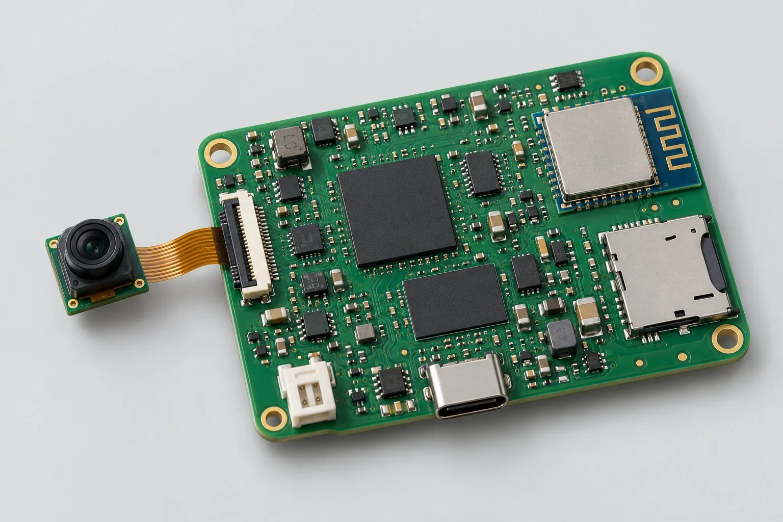
The pet video-recorder mainboard uses a video SoC or core module to connect the camera, storage, and Wi-Fi for event recording and wireless readout. Check encoding, frame rate, and write performance first, then review lens, battery, antenna, and thermal layout within the wearable board outline.
Custom development reference design. The following parameters are requirement configurations and design targets; validate functions and performance through agreed prototype tests.
| Functional Partition | Design and Inspection Objects |
|---|---|
| Camera and Audio | Define the camera, lens, and optional audio; select DVP or MIPI CSI-2 according to the processor, keeping the interfaces distinct. |
| Processor/image encoding | The video SoC/module must support the agreed resolution, frame rate, and encoding. The interface count of an ordinary wireless MCU does not establish recording capability. |
| Storage and wireless interface | Budget throughput and power separately for microSD/eMMC and Wi-Fi; Bluetooth is only an optional configuration interface. |
| Video Recording / Upload Function | Freeze the data flow for event triggers, prerecording, segmented files, and wireless readout; record dropped frames and peak buffer usage. |
| Battery and charging management | Review single-cell lithium-battery charging and fuel gauging under simultaneous recording and transmission; separate the SoC heat source from the battery. |
| Power Loss / Storage Recovery | If power fails, storage fills, or an approved card-removal event occurs during recording, flag damaged segments and recover. Repeat thermal-management and upgrade checks separately. |
How much does pet camera mainboard design cost, and how is it quoted?
Pet camera mainboard costs depend on video architecture, not just camera pixel count. Sensor interfaces, encoding, frame rate, storage, and file recovery after power loss determine hardware and software work; wireless readout and cloud recording are also different services. The quotation should specify board drivers, recording functions, testing with actual cameras, apps, and cloud services.
Quotation terms depend on the approved files, quantity, material supply, tests and delivery requirements.
Prepare a structured RFQ or use the short inquiry form.
| Quotation Items | What services are included | What to Check When Comparing Quotes |
|---|---|---|
| Circuit and PCB Design | Camera, encoding, and storage architecture | Reusable portions of existing designs and circuit/mechanical changes |
| Software and Validation | Wireless read, file management, and power-loss recovery | Board drivers, video files, wireless readout, phone interfaces, and cloud storage are separate scopes |
| Prototype Preparation | Bare PCB, BOM procurement, assembly, and agreed prototype quantity | Whether material/component revisions, prototype quantities, and test targets match |
| Subsequent Revision | Record new requirements separately from post-test corrections | How agreed changes, source files, and validation results are delivered |
Should pet cameras use video SoCs or wireless MCUs?
Check the sensor interface and video encoding capability first. An ordinary wireless MCU’s pin count does not replace encoding and storage budgets; select architectures separately for low-frame-rate imaging and continuous recording.
Is higher camera resolution always better?
Compare frame rate, bitrate, recording duration, and wireless transmission together. Higher resolution changes data and storage loads; select the configuration for actual viewing and recording tasks before choosing the processor.
Do camera-mainboard quotations include apps and cloud storage?
Board drivers, recording files, wireless readout, mobile interfaces, and cloud storage have different scopes. Explicitly include file recovery after power loss and readout testing in the quotation; operational services are not automatically included in mainboard development fees.
Reference configuration: camera to recording/wireless readout
| Configuration Field | Reference Configurations/Selections | Basis and Status |
|---|---|---|
| R&D Direction | Pet video recording and motion-trigger design reference | Illustrative design direction; requirements and prototype validation must be agreed |
| Reference Function | Event recording, storage, and wireless read | Design Objective |
| Camera Interface | DVP or MIPI CSI-2, depending on the processor | Design Objective |
| Video Target | 720p event recording target example | Design Objective |
| Main Controller Candidate | Video SoC/complete core module; confirm encoding first | Design Objective |
| Storage Configuration | Choose microSD or eMMC | Design Objective |
| Wireless Interface | Wi-Fi module; Bluetooth configuration only | Design Objective |
| Power Supply Objective | Single lithium battery plus charger/battery gauge | Design Objective |
| Stackup Candidate | 6–8 layers; evaluate HDI for constrained packages | Design Objective |
| Structural Constraint | Lens / Battery / Antenna Positioning Priority | Design Objective |
| Firmware Scope | Recording triggers, file recovery, heat management, upgrades | Design Objective |
| Verify Output | Video files, dropped frames, power consumption, temperature rise, and wear testing | Design Objective |
Video Encoding and Storage Routing
First confirm processor encoding and camera-driver capabilities; the interface count of a conventional wireless MCU cannot replace a video-link budget.
Event recording reduces the continuous operating duty cycle, but wake-up latency and prerecording requirements add buffering work.
microSD allows removal for readout, while eMMC suits fixed assembly; their power-loss handling and supply requirements differ.
Design budget and trade-off examples
Check design targets with engineering calculations
At an assumed 2Mbit/s, one hour's video payload is approximately 2×3600/8=900MB; variable bitrate also requires peak-write and container overhead budgets.
Conditions and Scope of Application:The encoder, resolution, and scene determine actual bitrate. Test storage cards, heating, file damage after power loss, and wireless bandwidth; do not directly promise battery life.
Replace examples with selected components and record margins; calculations support design choices, while prototype records support acceptance.
Power and layout for camera-to-recording/wireless access
- Place lens interfaces, fast storage, power in adjacent rigid regions; antennas at enclosure edges.
- Constrain camera differential channels according to the selected SoC; check continuous ground references and connector transitions together.
- Keep SoC hot spots away from the battery; jointly review thermal paths, shielding cans, and HDI pad structures.
Video recorder mainboard R&D input
- Recording duration/resolution/frame-rate targets and encoding format
- Camera/lens specifications, processor resources, software licenses
- Wearable weight, enclosure, battery, cooling, and data privacy requirements
If circuit files exist, provide editable schematics, PCB, BOM, and current issues, and agree on review or revision scope. If only functions are defined, freeze this page's inputs before selection and circuit development. Agree separately on control-software and external-application responsibilities, interfaces, and acceptance.
Video recorder mainboard milestone delivery
| phase | Engineering Work for This Proposal | Reviewable Deliverables |
|---|---|---|
| Requirements and Design Freeze | Freeze video format/frame rate/duration, processor resources, software licenses, and wearable structure | Functional/interface requirements, mechanical revision, acceptance conditions, and open items |
| Schematic and Component Selection | Design camera, video core, storage, wireless, battery power/sequencing | Editable schematics, controlled BOM, footprint checks, and design calculations for these circuits |
| Layout and Routing | Constrain image and high-speed storage signals; check package breakout and lens/antenna/battery locations | PCB source files, actual stackup/hole/net constraints, DRC, and assembly-dimension checks |
| Simulation/Calculation | Budget encode/write/upload peaks, prerecord buffers, task charge, enclosure heat | Design calculations/models, input conditions, margins, and items awaiting measurement |
| Prototype and Software | Build a video prototype and integrate event recording, file segmentation/recovery, and wireless readout | Manufacturing package, video mainboard prototype, agreed recording firmware, camera/encoding/storage configuration, and file recovery and upgrade instructions |
| Testing and Version Closure | Record motion triggers, dropped frames, and file recovery; check current and temperature rise during simultaneous recording and transmission | Procedures, wiring, raw results, and decisions for the prototype revision; include issue/change and limitation lists |
Video file and power loss recovery verification
- Motion recording, trigger latency, dropped-frame statistics
- File recovery after full storage/card removal/power loss
- Concurrent recording/wireless power and temperature rise
- Tests of the enclosed antenna, lens positioning, and resistance to movement
Record motion triggers, dropped frames, and file recovery; check current and temperature rise during simultaneous recording and transmission. Document equipment, conditions, revisions, and acceptance criteria in the report, including passed items and untested conditions.
Video-file and power-loss recovery worksheet
The table below breaks camera input, recording, and wireless readout into actionable checks. Freeze samples, equipment, environment, and allowable deviations before testing; link results to this revision’s raw records.
| Verification Object | Pre-Production Freeze | How to Test Prototypes in Practice | Delivery and Acceptance Records |
|---|---|---|---|
| Video Budget | Processor/camera, format, resolution, frame rate, and storage medium | Record while wirelessly reading; capture frame sequences/host throughput | Deliver continuous-recording, dropped-frame, and buffer-usage records; rated interface bandwidth does not establish encoding capability |
| File Recovery | Filesystem, segmentation, low-battery/card-removal behavior | Interrupt recording power, fill cards, perform approved removal | Retain playable segments, corrupt flags, recovery steps |
| Housing and Power Consumption | Lens fastening, antenna positions, battery/enclosure thermal targets | Run enclosed continuous recording/transmission and motion triggers | Record current, temperature rise, and trigger latency, identifying lens/enclosure and firmware revisions |
Manufacturing and assembly coordination for this design
- Clearly divide responsibilities for the camera FPC connector, clean lens assembly, and mainboard soldering.
- Record camera, storage, wireless, and firmware revisions in the fixture records; inspect critical BGA solder joints according to risk.
Link design revisions to schematics, BOM, PCB, fabrication, and software documentation. When fabricators adjust stackup, materials, or holes, or Assembly parties propose substitutions, recheck critical electrical and test conditions together.
View this functional board’s assembly and test configuration: pet video board PCB assembly and test configuration. Design covers source files, component selection, and validation targets; PCB assembly sources/receives materials, assembles, programs agreed files, and performs production tests against approved BOMs. This link opens a related assembly reference configuration; it does not establish a delivered product or a shared physical model.
Common questions on purchasing and customization
How much does pet camera mainboard design cost, and how is it quoted?
A project-specific quotation requires review of the available files, quantity, materials, requested tests, delivery destination, taxes, shipping, and trade terms. Any formula on this page organizes cost inputs; it is not a quoted rate.View cost items, calculation conditions, and sources.
Should pet cameras use video SoCs or wireless MCUs?
Check the sensor interface and video encoding capability first. An ordinary wireless MCU’s pin count does not replace encoding and storage budgets; select architectures separately for low-frame-rate imaging and continuous recording.
Is higher camera resolution always better?
Compare frame rate, bitrate, recording duration, and wireless transmission together. Higher resolution changes data and storage loads; select the configuration for actual viewing and recording tasks before choosing the processor.
Do camera-mainboard quotations include apps and cloud storage?
Board drivers, recording files, wireless readout, mobile interfaces, and cloud storage have different scopes. Explicitly include file recovery after power loss and readout testing in the quotation; operational services are not automatically included in mainboard development fees.
How should full-storage behavior be accepted on a camera board?
Define loop-overwrite or stop strategies, then check file directories, user indications, and wireless readout; retain the storage revision and boundary conditions.
What to Check When a Camera Suddenly Loses Power?
Check the current file, subsequent startup, and storage recovery; repeat testing in a fixed recording state and save original files.
How should pet-camera budgets divide recording tasks?
Freeze the frame rate, bitrate, duration, and triggers for the 720p event-recording example, then list camera/video SoC, storage, wireless readout, and battery/thermal work as four packages. Compare continuous recording or cloud upload as extensions; adding camera pixel specifications and wireless module prices does not establish the complete mainboard development fee.
What must customers provide for video-mainboard layout only?
Provide the selected processor, DVP or MIPI CSI-2 camera, encoding capabilities, microSD/eMMC, and power design; freeze lens, antenna, and battery positions. Layout implements the 6–8-layer or necessary HDI constraints. List unfinished camera drivers, file recovery, and recording scheduling as separate software work.
How should recording firmware and wireless readout interfaces be divided?
The board handles triggers, encoding, file directories, full-storage strategies, and recovery after power loss; the readout side handles browsing, downloading, or display. Existing customer mobile software can reduce interface development, but device protocols and file readout still require integration. A Bluetooth configuration option is not a video transmission link.
Which data budgets should video-mainboard source delivery include?
Deliver processor and camera interfaces, power design, storage layout, and mechanical revisions, with encoding/bitrate, trigger, and file strategies included in the software. Retain original videos, dropped-frame records, write performance, power consumption, and temperature-rise data. A 720p label without frame-rate and storage conditions is insufficient to support later revisions.
Which tasks need to be requoted when changing from microSD to eMMC?
Recheck processor support, packaging/buses, power, and layout, then update storage drivers, the file system, and upgrades. Existing event-recording logic may be reusable, but full-storage, power-loss, and wireless-readout tests must be repeated with the new component. Changing the storage name does not justify reusing all reports.
Can event-recording boards become all-day continuous cameras?
Continuous operation changes encoding, write, supply, and thermal loads, so recalculate recording duration and storage-space strategies. Parts of the camera interface and readout tools may be reusable, while dropped frames and temperature rise during continuous recording require separate verification. This page’s battery-powered event-recording target does not establish all-day operation.
How should I prepare an RFQ for pet-camera mainboard design?
Start with the target functions, application, and available files. An engineering quotation then confirms recording duration/resolution/frame-rate targets and encoding format; camera/lens specifications, processor resources, and software licenses; and wearable weight, enclosure, battery, cooling, and data privacy needs. For an existing circuit, provide editable schematics, PCB files, and BOM. For a faulty prototype, include its revision and reproduction records. List missing information as review tasks so both parties quote against the same assumptions.
How should pet camera mainboard prototype verification costs be compared by operating condition?
Fix the prototype quantity, revision, equipment, and source of acceptance criteria before comparing costs. Check at least these areas separately: video budget—freeze the processor/camera, format, resolution, frame rate, and storage medium, then record while reading wirelessly and capture frame numbers and host throughput; file recovery—freeze the file system, segmentation rules, low-battery behavior, and card-removal behavior, then test power loss, full cards, and approved card removal during recording; enclosure and power—freeze lens mounting, antenna position, battery, and enclosure thermal targets, then record/transmit continuously inside the enclosure and test motion triggers. State whether raw data and issue closure are included; one successful power-on does not constitute complete verification.
Compare related designs and plan the next step
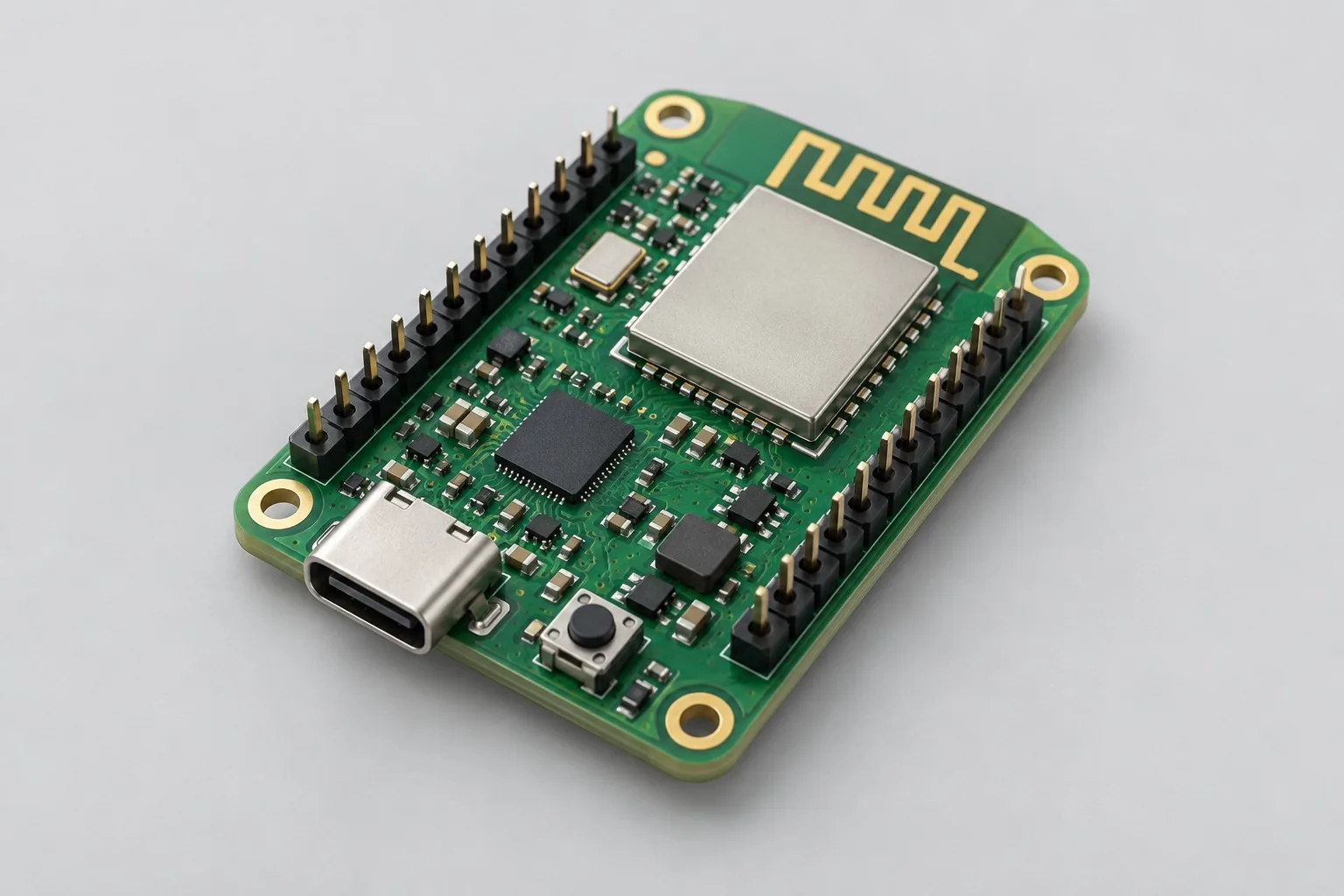
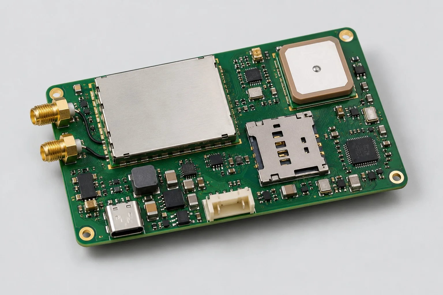
Compact Wi-Fi/Bluetooth communication core board design · Compact 4G/Bluetooth/GPS tracker design
Return HDI PCB design selection · Select solution by device function · Consult This Proposal R&D Team · Camera computing board HDI PCB fabrication
Documentation Basis and Boundaries
Engineering reference | ESP32-S3 PCB layout: power, RF, and antenna clearance: ESP32-S3 guidance is a reference only for the layout of wireless subcircuits actually used. It does not establish video SoC encoding, MIPI interface, or 720p performance; assess these against the actual processor/camera documentation.