
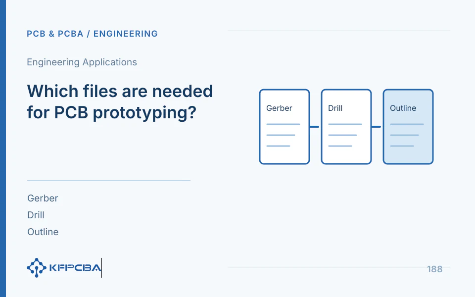
PCB prototyping files: layer, hole, and board-outline deliverables
Gerber describes circuit board artwork; manufacturing also requires drilling,Panel, Stackup and Process Requirements. X2 attributes can identify layer functions and object categories, while Gerber Job can convey manufacturing features such as board thickness and surface finish; check export tools and files for complete attribute support.
| Document | Content | Pre-Delivery Self-Check |
|---|---|---|
| Copper layer | Each Signal/Power/Ground Graphic | Consistent layer count, layer order, polarity, and units |
| Solder mask and silkscreen | Windowing, Marking, and Revision | Legends clear of pads, with openings corresponding to pads |
| Drilling/Milling Slots | Hole Coordinates, Hole Diameter, and Plating Attributes | Distinguish PTH/NPTH and each via layer pair |
| Panel | Complete outline and mechanical holes | Single closed outer outline, do not use screenshots as substitute |
| Manufacturing Instructions | Stackup, copper weight, surface finish, impedance, and acceptance | All in the same version as graphic files |
Check after export using a standalone viewer
Open layers individually, then overlay them: confirm coordinates and dimensions first, then check alignment of drill holes and pads, solder-mask openings, and board outline. Supply an explicit layer-mapping table for legacy formats without attributes; do not infer layer sequence from file extensions. List conflicts between engineering notes and fabrication drawings rather than leaving the manufacturer to choose.
Common Errors and Their Closure Methods
| Error | Impact | Resolution |
|---|---|---|
| Drill unit or zero suppression mismatch | Hole and pad offset or dimension misjudgment | Re-export and Verify Coordinates |
| Historical data or screenshots only | Unable to Accurately Generate Production Graphics | Add manufacturable graphics and drilling |
| Graphics and stackup versions differ | Layer Stackup/Impedance/Process Potential Errors | Freeze one complete package at the same revision |
| Ambiguous hole diameter definition | Drilling and finished size confusion | Specify Dimension Definitions and Tolerances in the Drill Drawing |
Inputs and outputs
Inputs are EDA exports, original engineering constraints, and fabrication notes; outputs are a complete file manifest, layer-by-layer inspection records, a gap list, and an approved revision. Confidential designs need not be uploaded to public viewers; authorized local tools can perform the same checks.
Prototype version management, Stackup Table, Submit Controlled Data Package · Engineering technology application
Engineering reference | Gerber manufacturing data: layer functions, drilling, and attributes: methodological reference; third-party design methods or material documentation do not represent KFPCBA manufacturing capabilities.
Engineering reference | Packaging PCB fabrication files: units, layer order, and engineering notes: reference for coordinate alignment, layer structures, and package completeness. Historical guide recommendations on file formats must be considered against current Gerber specifications and factory input requirements; they are not evidence of company capabilities.
Release methods that turn complete files into unambiguous information
The following manifest and checks are a delivery method compiled by the author. An archive opening successfully does not establish complete manufacturing documentation; identically named files may not come from the same export. Assign a revision to each formal release, retain the file manifest, export date, and verification records, and withdraw old packages from production. Ucamco's public descriptions distinguish image layers, object attributes, and Job manufacturing information, so checks should separately answer what the artwork represents, which layers holes connect, and what structure the board must have.
| Release Item | Fill Example | Questions to answer before release |
|---|---|---|
| Graphics and Layer Stackup | L1 copper, L2 reference, L3 power, L4 copper | Consistent names and attributes; missing or duplicate layers |
| Via Structure | Through-Holes, Non-Metalized Holes, Local Layer Pairs | Are Dimension Definitions and Start/End Layers Clear? |
| Manufacturing Instructions | Material, finished thickness, copper thickness, and surface finish | Same version as Job and drawing |
| Special Requirements | Impedance, via fill, outline and acceptance | Whether objects, locations, and sources of criteria can be identified |
Why hole diameters and via layer pairs cannot be inferred from extensions
Hole files must specify units, coordinate format, plating status, and layer pairs, and be overlaid with pads and board outlines. Finished-hole dimensions differ from production drill dimensions; one definition cannot be used as the other without explanation. Engineering calculation example: a through-hole lead has a maximum envelope of 0.80 millimeters and the drawing specifies a minimum finished hole of 0.90 millimeters, giving a geometric diameter difference of 0.10 millimeters. This is only a dimensional comparison; successful insertion also depends on shape, tolerances, hole position, and process, so it is not a general fit recommendation.
Blind and buried vias also need start/end layers, not merely diameters. If via layer pairs conflict with the stackup drawing, pause the affected work and raise questions so the approving party can release a complete, consistent package. CAM compensation or modifications proposed for fabrication should distinguish whether design intent is affected; changes to holes, nets, outlines, or materials require approval rather than being made solely for production convenience.
Reusable post-export checklist
- Open all layers and holes independently, first checking units and scale against known mechanical dimensions
- Overlay copper, holes, solder mask, and board outline to check offsets, mirroring, and closed boundaries
- Compare layer mapping and via layer pairs, checking whether attributes match file purposes
- Compare fabrication notes and Job data, recording missing, unsupported, or conflicting fields
- Confirm accepted formats and questions with the manufacturer; after resolution, resend the complete package and freeze its revision
How CAM questions and answers become traceable outputs
Issue records can follow location—current state—proposal—impact—approval—new revision. For example, if an outline slot has different widths in the artwork and mechanical drawing, attach its location and both values, then ask design to confirm the true requirement; do not independently select the wider value. Closure records include approval dates and effective packages, with conflicting files withdrawn. Formal delivery should also list unresolved items and paused scope, preventing emailed answers from failing to reach actual production files.
If only images exist, budget discussions can continue, but images cannot confirm all holes and layers. Source-file conversion and circuit reconstruction are also different tasks; define their deliverables and verification separately. Confidential designs can be checked in authorized local viewers; respect documentation permissions before using online tools. File checks establish package interpretability, not bare-board fabrication or electrical verification.
Source material and applicable scope
- Ucamco, Gerber Format; the public version page does not specify a revision number; checked 2026-10-17; sections: Gerber layer files, Attributes, and Job descriptions. Supports manufacturing artwork, attributes, and documentation responsibilities; the checklist is the author's compiled method.
- Ucamco, Gerber Job; the public version page does not specify a revision number; checked 2026-10-17; sections: manufacturing documentation and partial implementation notes. Supports manufacturing information such as board thickness, materials, and finishes, and format-support boundaries; does not replace supplier input agreements.
Can I get a quote or prototype using only a PCB screenshot?
Screenshots can help explain board outline and purpose but cannot directly establish holes, all copper layers, or actual connectivity. Budget estimates can start with layer count, dimensions, quantity, and materials; formal fabrication needs manufacturable files. If only physical boards or images remain, design reconstruction is required, with costs and deliverables different from Gerber-based PCB fabrication.
Compare costs and verification under the same conditions
State documentation status in the inquiry: an existing manufacturing package, an editable PCB file only, or a sample board only. List PCB fabrication, format preparation, and necessary reconstruction separately in quotes to avoid hiding file-preparation charges in bare-board unit prices.
View services and configurations related to this question or Request a project quotation. For initial discussions, describe the intended use, available documentation, and expected quantity.
Related procurement and acceptance Q&A
Can I get a quote or prototype using only a PCB screenshot?
See: Can I get a quote or prototype using only a PCB screenshot?
Can I place a formal order with Gerber files but no drill files?
The complete hole structure cannot be confirmed from these alone. Add hole coordinates, dimensions, plating status, and via layer pairs, then check against copper layers and board outline before freezing the manufacturing package.
See: PCB prototyping files: layer, hole, and board-outline deliverables
Gerber X2 versus legacy formats: must procurement choose X2?
The key is unambiguous layer functions, coordinates, and manufacturing information; legacy formats can include explicit layer mapping. Check exported results for complete X2 attributes; the format name alone does not support release.
See: Check exports with an independent viewer
If artwork conflicts with the stackup table, which should production follow?
Pause conflicting items first and have the authorized project party resolve revision differences, then issue a complete approved package. Do not leave the manufacturer to choose between artwork and notes.
View: Common Errors and Their Closure Methods
How do file-checking service deliverables differ from bare-board fabrication?
File preparation should deliver a manifest, layer-by-layer checks, and missing-item/revision records; fabrication follows the approved package. Source-file reconstruction or design changes require separate scope and cannot be replaced by one file check.
