Historical types · configuration reference
Pet training device PCBA: assembly configuration and test deliverables
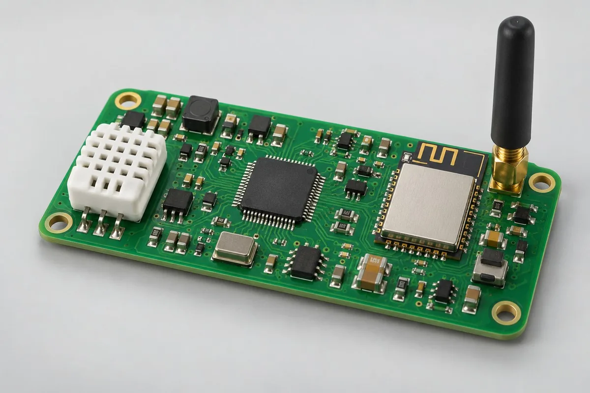
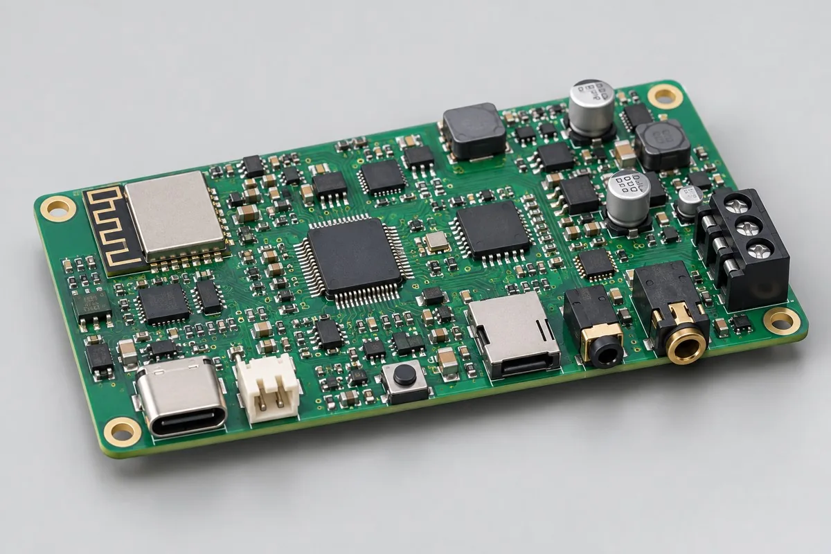
This illustrative wireless pet training receiver with sound, light, and vibration cues configuration supports engineering and procurement review. Power, interfaces, materials, firmware, and test conditions must be defined for the actual design. It is not evidence of a stocked model or a product developed or manufactured by KFPCBA. Approved files and order acceptance requirements govern.
Pet training device PCB assembly supports contract manufacturing and purchasing checks for reception of pet training commands and sound/light/vibration cues. First confirm the wireless receiver/MCU + cue drivers, buttons/pairing, buzzer/LED/vibration motor, and 2/4-layer FR-4 reference with separate antenna and driver zones. Then compare the scope of SMT → output/battery interfaces → pairing firmware → action testing and acceptance costs for pairing, each output, timeouts, low battery, and charging. This page separates the control board + pairing/level revision + action records from dog training/bark-control/dog deterrent/boundary deterrent product categories; this reference covers sound, light, and vibration. This helps determine whether a quotation covers the actual intended use. RFQ documentation reference:BOM · bare board · material supply
Reference specification and configuration options
| Options | Reference Configuration |
|---|---|
| Reference application | Dog training devices, bark-control devices, dog deterrents, and boundary deterrents |
| Power and Logic Domains | Rechargeable single-cell battery; independent output branches |
| Functional Module | Pet training command reception and sound/light/vibration cues |
| Core Components/Architecture | Wireless receiver / MCU + indicator driver |
| Interface and Channels | Buttons/pairing; buzzer/LED/vibration motor |
| Board Layers and Material Options | 2/4-layer FR-4 reference; separate antenna and driver zones |
| Component types | Wireless module/QFN, drivers, charging, and connectors |
| Assembly Route | SMT → output/battery interfaces → pairing firmware → action testing |
| Material Supply Scope | Output devices, antenna, and battery specified |
| Firmware and Parameters | Pairing identity, output levels, timeout, and lockout parameters |
| Test Focus | Pairing, each output, timeouts, low battery, and charging |
| Deliverables | Control board + pairing/level revision + action records |
| Configuration Limits/Options | Dog training/bark-control/dog deterrent/boundary deterrent categories; this reference covers sound, light, and vibration |
How much does pet training device PCB assembly cost, and what does the quotation include?
Wireless reception, vibration or sound/light outputs, charging, and battery interfaces affect training board costs. Itemize pairing identity, output levels, timeout lockout, and low-battery testing. Assemblies including motors or buzzers differ from boards alone. Developing automatic recognition functions is not routine programming.
Quotation terms depend on the approved files, quantity, material supply, tests and delivery requirements.
Prepare a structured RFQ or use the short inquiry form.
| Cost Item | Scope for This Configuration | Billing frequency and work scope | Procurement Verification |
|---|---|---|---|
| Bare PCB and core components | Wireless receiver/MCU + cue drivers; 2/4-layer FR-4 reference; separate antenna and driver zones | Price according to actual bare-board/component purchase quantities; authorize critical components and substitutions individually | Output devices, antenna, and battery specified |
| Placement and Post-Assembly | SMT → output/battery interfaces → pairing firmware → action testing | Feeder/program setup per lot; assembly priced per board, joint, or process as agreed, with counting rules specified | Wireless module/QFN, drivers, charging, and connectors |
| Manufacturing Preparation | Review stencils, first articles, and support tooling against the actual assembly route | New stencils/carriers may be separate one-time charges; verify panelization, revision, and condition before reuse | Reduced quantities do not automatically eliminate first-article or feeder setup |
| Functional Support | Pairing, each output, timeouts, low battery, and charging | Itemize test-method/fixture/script setup; agree execution charges per board, channel, or test duration | Separate supporting development from execution records for each board |
| Software and Parameters | Pairing identity, output levels, timeout, and lockout parameters | When firmware exists, distinguish file programming/verification from software development; omit programming without a firmware revision | Customer-approved files, parameters, and readback rules determine scope |
| Delivery and Change | Control board + pairing/level revision + action records; dog training/bark-control/dog deterrent/boundary deterrent categories; this reference covers sound, light, and vibration | Price accessories, retesting, and revision changes by approved work items; do not prefill fixed rates | Check BOM, tooling, programs, and acceptance revisions before reorders |
How do sound/light/vibration training boards differ from automatic bark-control boards?
This reference focuses on command reception and sound/light/vibration outputs. Automatic bark control also requires recognition inputs, decision logic, and validation. Product category names cannot replace implemented functions; purchasing should follow the actual circuit and firmware.
| Comparison Metric | Current Conditions | Factors Influencing Procurement Decision |
|---|---|---|
| Manufacturing Delivery | SMT → output/battery interfaces → pairing firmware → action testing | Produce boards/assemblies per BOM and assembly drawings; this does not establish that every system function passes |
| Functional Acceptance | Pairing, each output, timeouts, low battery, and charging | Compare unit prices after defining test stimuli, limits, accessories, and records; review missing test inputs first |
| Configuration Options | Buttons/pairing; buzzer/LED/vibration motor; 2/4-layer FR-4 reference; separate antenna and driver zones | Confirm circuit/program compatibility before reviewing assembly and test costs for interface, stackup, or component changes |
| Delivery Scope | Dog training/bark-control/dog deterrent/boundary deterrent categories; this reference covers sound, light, and vibration | Complete-system accessories, application development, and project verification are not automatically included in board assembly |
Should training device output components be onboard or external?
Onboard components reduce wiring but transmit vibration to the board. External components offer mechanical layout flexibility but add contacts and mounting work. Select pairing, output levels, action limits, and battery states together. Voltage changes cannot replace controlled level design.
- First list the required pet training command reception and sound/light/vibration cues. Distinguish build-to-print manufacturing, configuration changes, and new feature development.
- Then freeze complete part numbers for the wireless receiver/MCU + cue drivers, buttons/pairing, buzzer/LED/vibration motor, and the 2/4-layer FR-4 reference with separate antenna and driver zones. Separate consigned and sourced items according to the specified output components, antenna, and battery.
- Use the first article to verify SMT → output/battery interfaces → pairing firmware → action testing, along with pairing identity, output levels, timeout, and lockout parameters. If only firmware files are supplied, agree on programming verification first; review development separately.
- Convert pairing, each output, timeouts, low battery, and charging into acceptance items with stimuli, limits, and records. Define fixture ownership, testing of each board, and retesting after rework.
- Finally confirm the control board + pairing/level revision + action records and dog training/bark-control/dog deterrent/boundary deterrent categories. This reference covers sound, light, and vibration. Compare total prices using the same quantity, accessories, and test scope, then freeze the order version.
Applicable uses and situations requiring separate review
Sound/light/vibration cues for pets and reception of authorized wireless training commands.
This page provides no electrical stimulation, high-energy acoustic output, or animal safety outcome commitments. If automatic bark control requires sound recognition, define sensing and algorithms separately. A basic receiver board cannot be described as a validated recognition system.
Assembly Challenges for This Product
Vibration motor current and mechanical vibration can affect connectors and wireless power supplies. Check outputs separately before combined operation. Prevent output interface misconnection, make pairing states explicit, and test maximum action time and low-battery lockout after programming.
Structural, thermal, and configuration trade-offs
Integrated motors/buzzers simplify wiring but transmit vibration to the board. External wiring offers mechanical placement flexibility but increases loosening risk. Multiple output levels require controlled parameters; battery voltage changes cannot replace level design.
Product-specific test matrix
| Test stage | Inspection/Functional Methods | Acceptance Record |
|---|---|---|
| Pairing Communication | Authorized transmitter pairing / unbinding / reconnection | Identity and reception status |
| Indicator Output | Sequential operation of audible/visual and vibration with duration verification | Level, actions, and stop results |
| Exception Status | Low battery, repeated command, and timeout | Lock/recovery, program version |
Defect Handling and Acceptance
Assess mismatched pairing identities, reversed motors, driver solder bridges, and timeout failures separately. Acceptance emphasizes stopping capability and false-trigger control. Animal behavioral outcomes require system/use evaluation and cannot be guaranteed by PCBA action testing.
Pet training PCBA: material supply and version control
Lock electrical/mechanical models for cue components and motors. Customer-supplied batteries require protection and interface definitions. Check bands, pairing protocols, and regional conditions for wireless substitutions. Assign production identities through an authorized process.
Prototype and production planning
Test mechanical vibration and action levels on prototypes. Prevent pairing identity mix-ups in production, record output parameters, and retest buttons and cues after enclosure assembly. Product categories do not constitute a stock feature list.
Delivery Configuration
Control board + pairing/level revision + action records. Dog training/bark-control/dog deterrent/boundary deterrent categories; this reference covers sound, light, and vibration.
Convert this configuration into a reviewable order
For pet training device control board orders, verify the BOM, quantity, material supply, and conditions below. Provide the pick-and-place file/CPL, DNP list, and assembly drawing for this board's SMT process. For contracted programming, provide files, programming rules, and verification requirements for pairing identity, output levels, timeout, and lockout parameters. Review costs separately for materials, SMT → output/battery interfaces → pairing firmware → action testing, and required stencil/loading, support carriers, and test resources. Reapprove versions after documentation changes, and agree on delivery milestones once material readiness and scheduling are confirmed.
| Required project inputs | Engineering Decisions Affected | Records/delivery as agreed in the order |
|---|---|---|
| Audio, Light, and Vibration Output | Provide the reception protocol, actuators, and maximum output/duration, and freeze handling rules for communication loss and false triggers. | Record each cue level, timeout, and communication-loss behavior. The reference configuration does not introduce undefined stimulation outputs. |
| Wearable Structure | Include accidental-operation prevention, buttons, and sealed assembly details, and specify board-only or complete-set delivery. | Verify assembly and functions on the first article. Environmental ratings require specified testing and cannot be inferred from enclosure appearance. |
Pet training device PCB assembly FAQ
How much does pet training device PCB assembly cost, and what does the quotation include?
Itemize wireless reception, cue drivers, pairing, output levels, and timeout/battery-state tests. Confirm the files, quantities, material responsibilities, test records, delivery destination, currency, taxes, shipping, and trade terms before comparing totals. Review the quotation scope.
Does a training device PCBA quotation include automatic recognition firmware?
Separate customer firmware programming from recognition algorithm development. Sound/light/vibration action testing verifies output links but does not establish completed animal behavior recognition or outcome validation.
Are timeout and low-battery tests still needed after successful pairing?
Pairing verifies only part of communication. Continuous-action limits and low-battery lockout are independent states. Record each output and abnormal stop so motor operation does not conceal parameter errors.
How can incorrect parameter loading be prevented for multilevel training device outputs?
Maintain firmware by pairing identity, output-level revision, maximum action time, and lockout state, with records for each output. Battery voltage changes are not controlled levels. Read back shipment parameters and verify their association.
How do consigned batteries and motors affect training board costs?
Consignment reduces purchasing scope, but interfaces, reverse-connection protection, mounting, and combined operation still require testing. Motor current and mechanical vibration affect wireless operation and connections. SMT pricing cannot be based solely on component count.
How should pairing communication testing be included in purchasing acceptance for pet training device PCB assembly?
The reference method for this configuration pairs/unpairs/reconnects with an authorized transmitter. Records should include identities and reception states. Provide test inputs, applicable configurations, and acceptance limits with the RFQ, then agree on the scope of first-article verification and testing of each board. Price test preparation separately from each execution. If limits are missing, the method can be reviewed first, but completing a procedure cannot be described as meeting performance requirements.
How should cue output testing be included in purchasing acceptance for pet training device PCB assembly?
The reference method for this configuration runs sound/light/vibration at each level and checks duration. Records should include levels, actions, and stopping results. Provide test inputs, applicable configurations, and acceptance limits with the RFQ, then agree on the scope of first-article verification and testing of each board. Price test preparation separately from each execution. If limits are missing, the method can be reviewed first, but completing a procedure cannot be described as meeting performance requirements.
How should abnormal-state testing be included in purchasing acceptance for pet training device PCB assembly?
The reference method for this configuration covers low battery, repeated commands, and timeouts. Records should include lockout/recovery and firmware version. Provide test inputs, applicable configurations, and acceptance limits with the RFQ, then agree on the scope of first-article verification and testing of each board. Price test preparation separately from each execution. If limits are missing, the method can be reviewed first, but completing a procedure cannot be described as meeting performance requirements.
Which actions need shipment verification after changing a training board from test pairing identity to production identity?
Bind the production identity to the approved transmitter, output levels, maximum action duration, and lockout parameters. After switching, read back the configuration and recheck pairing/unpairing, sound/light/vibration at each level, repeated commands, timeouts, and low-battery states. Price programming and actual execution separately. This reference covers sound, light, and vibration only. New recognition logic or other outputs require separate design and acceptance and cannot reuse the original action records.
Must first-article, stencil, and loading charges be recalculated for repeat pet training device PCB assembly orders?
The process for this configuration is SMT → output/battery interfaces → pairing firmware → action testing. For SMT, verify the stencil and panelization; for through-hole or later-installed parts, verify support and assembly methods. Agree on loading and first-article work for this batch. Reuse existing tooling only when its version, position, and condition match. After changing components or interfaces in the wireless module/QFN, drivers, charging circuitry, or connectors, first review effects on tooling and pairing, each output, timeouts, low battery, and charging, then confirm repeat charges.
How should total prices be compared when critical parts are consigned and the remaining materials are sourced for pet training device PCB assembly?
Create a purchasing responsibility matrix using this page's specified output components, antenna, and battery. Confirm complete part numbers, quantities, packaging, and excess-material rules with the materials. Consignment only changes purchasing responsibility. SMT → output/battery interfaces → pairing firmware → action testing, along with pairing, each output, timeouts, low battery, and charging tests, remain actual work. Approve the effects of shortages, substitutions, or lot changes first. Do not directly compare consigned-material unit prices with complete assembly prices that include materials.
Which tests should be repeated after rework or supplemental pet training device PCB assembly orders?
Select retests based on the effects of the change. Original acceptance items for this configuration are pairing, each output, timeouts, low battery, and charging; shipment records comprise the control board + pairing/level revision + action records. When rework affects power, interfaces, critical analog circuitry, or software versions, check related tests rather than only the repaired solder joint. Align supplemental orders with the original BOM, parameters, and test resources. Agree on retest charges based on approved items and actual quantities tested, without assuming free service or a fixed turnaround.
Compare Other Products in This Category
- Smart home sensing control board: Wireless sensing and low-power wake-up.
- Portable Audio Control Board: Charging, digital audio, and amplifier.
- 4G Bluetooth GPS locator control board: type, communication/positioning/battery-life trade-offs.
- Pet video recording control board: recorder/DV type, camera/storage thermal loads.
- Smart fish tank feeding control board: type, feeder motor and water-level states.
Return to consumer-electronics PCB assembly configuration comparison · Component Supply and Procurement · Testing and Delivery Scope
Material and Process Reference
- Engineering reference | SMT packages and assembly methods: pads, stencils, and thermal processes: a package/assembly method index only; not evidence that the product configurations on this page are models produced by KFPCBA