Engineering reference design · prototype validation pending
Low-power sensor design: environmental acquisition to wired readout
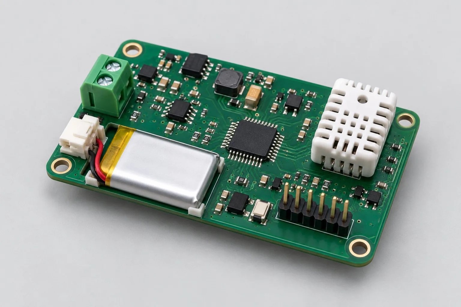
The battery-powered sensor node acquires temperature/humidity and one external analog input, wakes periodically, buffers records, and reads them through a wired service interface. It suits environmental monitoring without continuous networking; budget wireless and RS485 expansion power separately.
Custom development reference design. The parameters below are requirement configurations and design targets; validate product performance through agreed prototype tests.
| Functional Partition | Design and verification scope |
|---|---|
| Environmental/analog sensing | Define temperature/humidity sensor mounting, external analog signal types/ranges, and acquisition intervals for battery-node use. |
| Conditioning and Sensor Interfaces | Check I²C sensor power, analog conditioning, and input protection; voltage and bridge inputs need distinct front ends. |
| Low Power MCU | A low-power MCU manages RTC wakeup, acquisition, thresholds, and storage, recording stage durations and power-loss strategies. |
| Wired Read Interface | UART supports service readings/configuration; assess external supply and backfeeding separately for RS485. |
| Battery and Low Power Supply | Switch off sensor power domains while retaining wakeup domains; measure operating, sleep, and undervoltage currents rather than MCU typical values alone. |
| Wake-up/sampling timing | Sample after sensor stabilization, write buffers, then sleep; disconnection, low battery, and full storage each need identifiable states. |
How much does low-power sensor board design cost, and how is it quoted?
Effort centers on task timing and measured power: periodic acquisition, event wakeup, and continuous monitoring need different power control and software. Existing sensing circuits allow separate power-domain revisions and state-current measurements; new development also includes sensor selection, interfaces, and prototype validation. List battery purchase costs separately from development.
Quotation terms depend on the approved files, quantity, material supply, tests and delivery requirements.
Prepare a structured RFQ or use the short inquiry form.
| Quotation Items | What services are included | What to Check When Comparing Quotes |
|---|---|---|
| Circuit and PCB Design | Sensor enable, wakeup timing, and sleep-current measurement | Reusable portions of existing designs and circuit/mechanical changes |
| Software and Validation | Battery condition and sampling cycle verification | Agree separately on state currents, wakeup waveforms, sensor power-on stabilization, and periodic-task charge |
| Prototype Preparation | Bare PCB, BOM procurement, assembly, and agreed prototype quantity | Whether material/component revisions, prototype quantities, and test targets match |
| Subsequent Revision | Record new requirements separately from post-test corrections | How agreed changes, source files, and validation results are delivered |
Should low-power sensor boards wake periodically or acquire continuously?
Compare periodic wakeup for slow-changing quantities permitting interval reads; retain monitoring for events requiring continuous detection. Include sensor stabilization, communication time, and leakage in task-charge budgets rather than MCU sleep current alone.
Does increasing battery capacity solve battery-life problems?
Measure acquisition, processing, communication, and sleep currents first. Larger capacity does not remove always-powered sensor or regulator losses. Integrate actual wake duration before choosing battery, sampling intervals, and power-domain control.
Which power tests should low-power board design quotations include?
Agree separately on state currents, wakeup waveforms, sensor power-on stabilization, and periodic-task charge. Battery-life assessment also needs battery conditions, temperatures, and usage cadence; layout files alone do not establish battery-life validation.
Reference configuration: environmental acquisition to wired readout
| Configuration Field | Reference Configurations/Selections | Basis and Status |
|---|---|---|
| Finished Product Function | Temperature/humidity acquisition + 1 external analog sensor | Design Objective |
| Power Supply Configuration | Two AA batteries as a requirement example | Design Objective |
| Sampling interval | Wake every 60 seconds; configurable acquisition interval | Design Objective |
| Sensor Interface | 1 channel I²C + 1 channel ADC input | Design Objective |
| External Communication | UART service port; RS485 as a separately powered expansion option | Design Objective |
| Core Component | Low-power MCU, digital temperature/humidity sensor, load switches | Design Objective |
| Layer Stackup Plan | 2 layer FR-4; no dense BGA | Design Objective |
| Power Strategy | Switchable sensor domains; RTC/wakeup domain remains powered | Design Objective |
| Event Function | Threshold alarms, disconnection detection, low-battery indication | Design Objective |
| Storage Configuration | Internal Flash ring buffer or external EEPROM | Design Objective |
| Structural Objective | Ventilated sensing window; battery compartment away from temperature sensor | Design Objective |
| Validation outputs | Operating/sleep current waveforms and battery-budget table | Design Objective |
Wake-up acquisition and battery budget
Periodic acquisition reduces continuously powered time; first establish a battery-life budget using wake duration and the integral of actual current.
Analog inputs may use divided-voltage acquisition or bridge-sensor conditioning; do not share unevaluated input ranges between them.
Wireless transmission adds modules and peak-current budgets; this node's offline configuration does not establish wireless battery life.
Design budget and trade-off examples
Check design targets with engineering calculations
Waking every 60 seconds, running at 10mA for 0.2 seconds and 10μA for the remaining 59.8 seconds gives average current approximately (10×0.2+0.01×59.8)/60=0.0433mA.
Conditions and Scope of Application:This excludes sensors, regulator losses, and battery self-discharge. Measure usable capacity and temperature/pulse capability separately; this value cannot promise battery life.
Replace examples with selected components and record margins; calculations support design choices, while prototype records support acceptance.
Power and layout for environmental acquisition to wired readout
- Keep temperature sensing away from regulators, battery heat, and copper heat-spreading paths; coordinate board openings with enclosure airflow.
- Use short high-impedance analog traces and consider guard rings; test pads must not add significant leakage.
- Retain current-measurement jumpers for each power domain; protect UART interfaces against backfeeding when powered off.
Sensor Node R&D Input
- Sensor measurement ranges, sampling intervals, permitted response time
- Battery chemistry, operating temperature, replacement method
- Enclosure vents, field condensation, and contact-contamination conditions
If circuit files exist, provide editable schematics, PCB, BOM, and current issues, and agree on review or revision scope. If only functions are defined, freeze this page's inputs before selection and circuit development. Agree separately on control-software and external-application responsibilities, interfaces, and acceptance.
Sensor Node Phase Deliverables
| Stage | Engineering Work for This Proposal | Reviewable Deliverables |
|---|---|---|
| Requirements and Design Freeze | Agree on sensing ranges, sampling intervals, battery chemistry, and enclosure sensing windows | Functional/interface requirements, mechanical revision, acceptance conditions, and open items |
| Schematic and Component Selection | Design sensor conditioning, low-power domains, RTC wakeup, and storage circuits | Editable schematics, controlled BOM, footprint checks, and design calculations for these circuits |
| Layout and Routing | Separate sensors from heat sources, control high-impedance leakage, and place domain-current test points | PCB source files, actual stackup/hole/net constraints, DRC, and assembly-dimension checks |
| Simulation/Calculation | Integrate charge over wakeup, stabilization, sampling, and writing durations; assess errors and usable battery capacity | Design calculations/models, input conditions, margins, and items awaiting measurement |
| Prototype and Software | Build node prototypes and integrate periodic acquisition, buffering, wired readout, and undervoltage recovery | Manufacturing Files, wired-interface node prototypes, agreed acquisition firmware, record formats, parameters, and current-measurement instructions |
| Testing and Version Closure | Calibrate environmental and analog inputs, record task charge, and validate disconnection, full storage, and power loss during writes | Procedures, wiring, raw results, and decisions for the prototype revision; include issue/change and limitation lists |
Sensor node power consumption and data validation
- Compare with calibrated instruments at room temperature and during temperature changes
- Integrate current separately during wakeup, acquisition, writing, and sleep
- Data recovery after disconnection, undervoltage, and full storage
- Sampling drift and restart at different battery voltages
Calibrate environmental and analog inputs, record task charge, and validate disconnection, full storage, and power loss during writes. Record equipment, conditions, revisions, and criteria in reports, identifying passed and uncovered items.
Sensor-node power and data validation worksheet
The table below turns environmental acquisition and wired readout into executable checks. Freeze samples, equipment, environment, and permitted deviations before execution; link results to this revision's raw records.
| Verification Object | Pre-Production Freeze | How to Test Prototypes in Practice | Delivery and Acceptance Records |
|---|---|---|---|
| Sampling Accuracy | Sensor types, measurement ranges, calibration points, and permitted errors | Compare against calibrated references at agreed temperature/humidity points, recording battery voltage simultaneously | Deliver raw readings, reference values, and correction coefficients; list sensor rated error separately from whole-board error |
| Battery Budget | Sampling/upload intervals, standby mode, usable battery capacity, and target battery life | Capture current-versus-time traces for wakeup, sampling, writing, and sleep | Integrate charge per task and list self-discharge/temperature assumptions; separate battery-life estimates from actual operating records |
| Record Recovery | Storage capacity, record format, and undervoltage-write strategy | Interrupt power during writes and simulate full storage and sensor disconnection | Check complete records, corrupt-record flags, and restart counts; do not treat disconnected readings as valid measurements |
Manufacturing and assembly coordination for this design
- Include sensing windows and board-edge clearances in mechanical drawings; consider post-solder cleaning residues at high-impedance inputs.
- Separate fixture logic power from current testing so fixture leakage does not mask sleep current.
Link design revisions to schematics, BOM, PCB, fabrication, and software documentation. When fabricators adjust stackup, materials, or holes, or Assembly parties propose substitutions, recheck critical electrical and test conditions together.
Common questions on purchasing and customization
How much does low-power sensor board design cost, and how is it quoted?
A project-specific quotation requires review of the available files, quantity, materials, requested tests, delivery destination, taxes, shipping, and trade terms. Complete development separately prices circuits, firmware, prototypes, and verification. Any formula on this page organizes cost inputs; it is not a quoted rate.View cost items, calculation conditions, and sources.
What should low-power board power reports record?
Record battery/external supply conditions, state currents, wake duration, sampling intervals, and sensor configuration so task charge can be recalculated.
What is needed to move low-power nodes from prototypes to small batches?
Freeze sensor revisions, power components, and firmware parameters; retain state-current inspections and readout tests so substitutions do not change sleep losses.
How should a low-power node budget be staged?
First develop basic temperature/humidity and single-channel analog reads, then power-domain shutdown and task-timing measurements every 60 seconds, and finally choose battery and buffering approaches. These three packages deliver readings, state-current waveforms, and task-charge tables. Measuring always-on losses first defines development scope better than buying larger batteries first.
Which low-power conditions are needed for two-layer layout-only work?
Beyond schematics and board outline, provide load-switch enables, always-powered RTC domains, sensor stabilization times, and sleep pin states. Layout engineers can then check backfeeding and battery loops; low-cost routing without these constraints does not replace board-level power review.
Is changing UART service access to RS485 simply adding a transceiver?
RS485 is a separately powered expansion option here. Recalculate transceiver standby, bus bias, wakeup, and protection consumption and define polling timing. Retaining UART diagnostics can reduce tool development, but added bus hardware and task-charge measurements remain separate items.
Which source code and parameters should low-power boards deliver?
Agree on configuration and source code for sensor startup delays, acquisition intervals, domain-enable sequences, buffer writes, and low-battery thresholds. Retain power domains and current-measurement access in hardware sources. Deliver raw current waveforms so interval changes permit reintegration rather than reusing one average.
Which work must be repeated after replacing temperature/humidity sensors?
Check addresses, drivers, supply ranges, stabilization times, and sleep states. Replacements can shorten or lengthen wakeup, requiring new readings, task-charge, and sensing-window thermal-coupling measurements. Compatible packages may reduce PCB changes but do not eliminate driver and battery-budget regression.
Can a basic sensor node become a continuous-alarm device?
Distinguish 60-second acquisition from events requiring continuous detection. Continuous detection may need always-powered comparators or interrupt paths, increasing charge demand. Existing RTC and periodic buffers may remain, but redefine detection latency, battery conditions, and false-alarm tests; periodic-node battery estimates do not transfer directly.
How should I prepare an RFQ before commissioning low-power sensor board design?
Initially describe target functions, application, and existing files. Engineering quotations further confirm sensor ranges, sampling intervals, and response times; battery chemistry, temperature, and replacement; enclosure vents, condensation, and contact contamination. Provide editable schematics, PCB, and BOM for existing circuits, and revisions/reproduction records for faulty prototypes. List documentation gaps as review tasks so quotations do not use different assumptions.
How should low-power sensor board prototype validation costs be compared by operating condition?
Freeze prototype quantity, revision, equipment, and criteria sources first. Separately check sampling accuracy: freeze sensor types, ranges, calibration points, and errors, compare calibrated references at agreed temperature/humidity points, and record battery voltage. For battery budgets, freeze sampling/upload intervals, standby, usable capacity, and life targets, then capture wakeup/sampling/writing/sleep current traces. For record recovery, freeze storage, formats, and undervoltage-write strategies, interrupt writes, and simulate full storage and disconnected sensors. State whether raw data and issue closure are delivered; one power-on pass is not complete validation.
Compare related designs and plan the next step
24V four-channel relay control board design · Timed pet feeder control board design
Return single/double-sided PCB design selection · Select solution by device function · Discuss your design requirements
Documentation Basis and Boundaries
Engineering reference | TPS22918 Chinese-language device reference: selection conditions and board-level validation: TPS22918 references sensor power-domain switches only; sensing accuracy, MCU sleep, and usable battery capacity need separate documentation and measurements.