Engineering reference design · prototype validation pending
Relay control board design: discrete I/O and RS485 to dry contacts
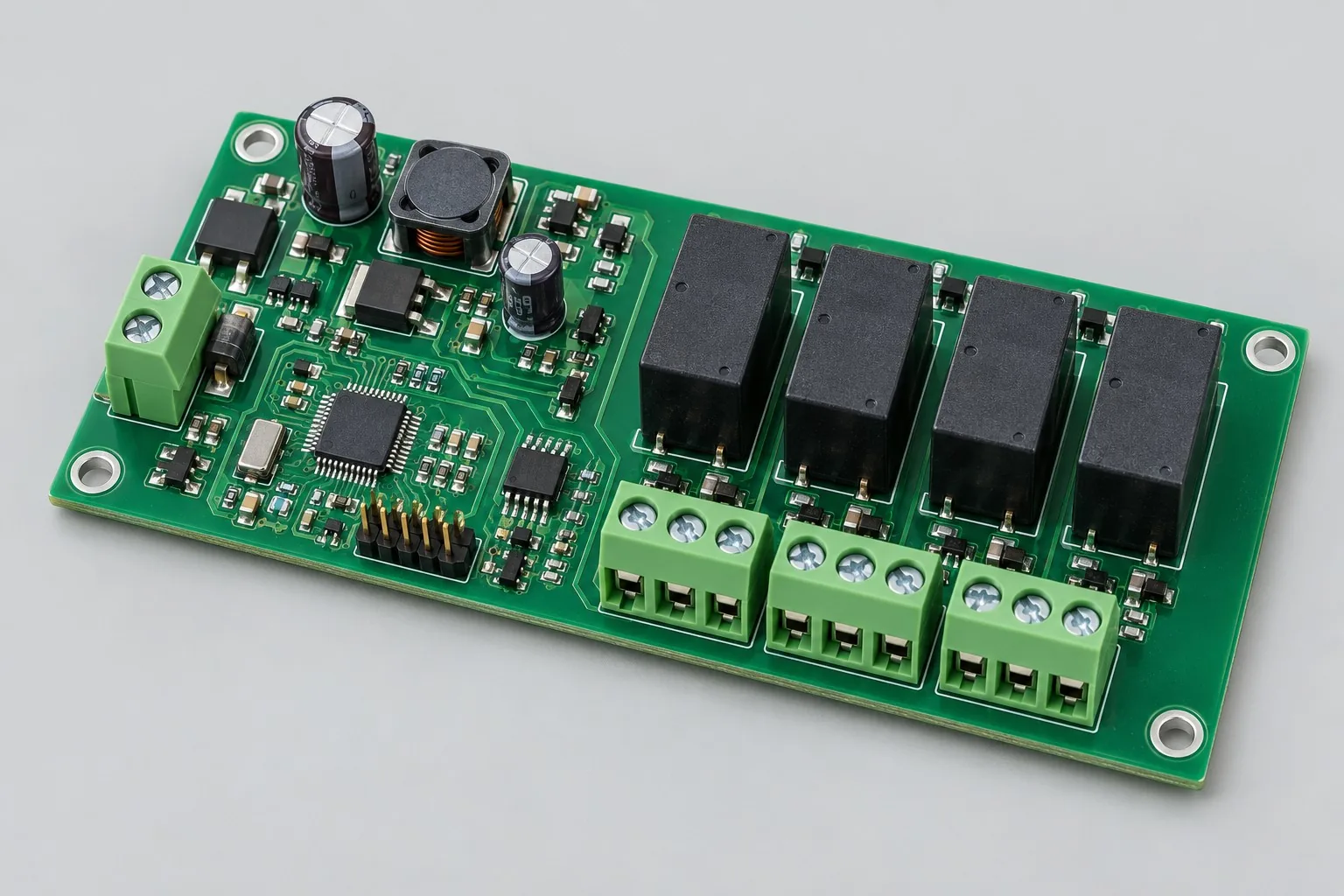
The four-channel relay control board converts 24V discrete inputs and RS485 commands into four dry-contact outputs and reads back control states. For cabinet auxiliary equipment, fans, or valves, confirm each channel's low-voltage loads, interlocks, and communication-loss outputs first.
Custom development reference design. The parameters below are requirement configurations and design targets; validate product performance through agreed prototype tests.
| Functional Partition | Design and verification scope |
|---|---|
| Discrete I/O / RS485 | Define active levels, debounce times, and RS485 addresses for 4 channels of 24V inputs; choose isolated or shared-ground inputs according to field grounding. |
| MCU and Output Status | The controller converts inputs and bus commands into output states, defining interlock priority, watchdog behavior, and communication-loss defaults. |
| Four-Channel Relay Drivers | Check relay coil voltage, drive current, and flyback paths; drive readback does not establish actual contact-continuity feedback. |
| Low Voltage Load Terminal | List each load's voltage, current, and inductive characteristics to select contacts and terminals, distinguishing logic ground from dry contacts. |
| 24V Protection and Voltage Regulation | Check reverse-polarity protection and fusing at the 24V input, the 5V coil domain, and 3.3V logic domain; measure supply behavior during simultaneous actuation and load switching separately. |
| Flyback/contact protection | Design coil flyback and contact-side suppression separately, checking switching interference, contact sticking, and power-loss states for actual loads. |
How much does relay control board design cost, and how is it quoted?
Relay-board costs extend beyond four-channel switching routing. Contact loads, channel interlocks, and whether outputs hold or switch off after RS485 loss all change driver circuits and firmware tests. List channels, terminals, concurrent power requirements, and load conditions first, then compare circuit development, protocol software, and prototype costs separately.
Quotation terms depend on the approved files, quantity, material supply, tests and delivery requirements.
Prepare a structured RFQ or use the short inquiry form.
| Quotation Items | What services are included | What to Check When Comparing Quotes |
|---|---|---|
| Circuit and PCB Design | Relay channels, contact loads, and interlock logic | Reusable portions of existing designs and circuit/mechanical changes |
| Software and Validation | RS485 registers, communication-loss states, and loaded integration | Hardware layout and protocol firmware such as Modbus are separate work items |
| Prototype Preparation | Bare PCB, BOM procurement, assembly, and agreed prototype quantity | Whether material/component revisions, prototype quantities, and test targets match |
| Subsequent Revision | Record new requirements separately from post-test corrections | How agreed changes, source files, and validation results are delivered |
How should relay and MOSFET control boards be selected?
Compare relays first when dry contacts and electrical separation on the load side are needed; compare MOSFETs or solid-state switches for frequent switching. Drives, flyback paths, temperature rise, and failure states differ, so switching-component prices alone are insufficient.
Will changing four channels to eight double design costs?
Costs do not simply scale with channel count. Added channels increase drives, terminals, concurrent power, and testing, while controller and communication circuits may be reusable. Separate reusable circuits from added-channel layout, firmware, and validation in quotations.
Does relay control board design pricing include RS485 software?
Hardware layout and protocol firmware such as Modbus are separate work items. For remote control, include register mapping, interlocks, power-loss defaults, and communication-loss tests in the commission rather than receiving only manufacturable PCB files.
Reference configuration: discrete I/O and RS485 to dry contacts
| Configuration Field | Reference Configurations/Selections | Basis and Status |
|---|---|---|
| Finished Product Function | 4-channel relay switching with status readback | Design Objective |
| Operating Input | 24V DC nominal; reverse-polarity protection and input fuse position | Design Objective |
| Digital Input | 4 channels of 24V discrete inputs through current limiting and isolation or level conversion | Design Objective |
| Output Boundary | 4 dry-contact outputs; select contact voltage/current from load specifications | Design Objective |
| Communication Interface | 1 RS485 port, with Modbus RTU as a protocol option | Design Objective |
| Core Component | STM32-class MCU + RS485 transceiver + low-side drivers | Design Objective |
| Layer Stackup Plan | Start with 2-layer FR-4; separate contact and logic regions | Design Objective |
| Power tree | 24V → 5V relays/peripherals → 3.3V logic | Design Objective |
| Protection Configuration | Coil flyback, bus TVS, power-loss safe states | Design Objective |
| Structural Objective | Same-side terminal exits; mounting holes match cabinet DIN-rail hardware | Design Objective |
| Firmware Function | Address settings, debounce, watchdog, output interlocks | Design Objective |
| Test Interface | SWD, 3.3V/5V test points, relay-drive readback | Design Objective |
Relay output interlock and lost connection status
Mechanical relays retain dry-contact isolation; response speed and life depend on the load. Use MOSFETs or solid-state relays for high-frequency switching loads.
Choose isolated or shared-ground input versions by field grounding; terminal markings must distinguish contacts, coil supply, and logic ground.
Firmware switches to preset safe outputs after communication loss; equipment processes define safe states.
Design budget and trade-off examples
Check design targets with engineering calculations
For four relays drawing 30mA per coil, simultaneous actuation requires 4×30=120mA; adding 60mA for control circuits gives 180mA steady state.
Conditions and Scope of Application:Coil and control currents are budget examples only; also check actuation transients, supply tolerances, and contact loads. Load current is not part of the coil-supply budget.
Replace examples with selected components and record margins; calculations support design choices, while prototype records support acceptance.
Power and layout for discrete I/O and RS485 to dry contacts
- Arrange terminals → protection → input conditioning along board edges; relay coil currents must not flow through MCU return paths.
- Plan contact-side isolation slots, keepouts, and spacing from load operating voltages; low-voltage logic spacing cannot cover mains versions directly.
- Retain continuous logic ground in 2-layer routing; route cross-region signals through isolators rather than under contacts.
Relay control board development input
- Rated/startup currents and inductive characteristics of four loads
- Cabinet 24V limits, cable lengths, grounding method
- Terminal/mounting-hole mechanical drawings and communication-loss output state tables
If circuit files exist, provide editable schematics, PCB, BOM, and current issues, and agree on review or revision scope. If only functions are defined, freeze this page's inputs before selection and circuit development. Agree separately on control-software and external-application responsibilities, interfaces, and acceptance.
Relay control board phase delivery
| Stage | Engineering Work for This Proposal | Reviewable Deliverables |
|---|---|---|
| Requirements and Design Freeze | Freeze four loads, command priority, interlock tables, and terminal/cabinet dimensions | Functional/interface requirements, mechanical revision, acceptance conditions, and open items |
| Schematic and Component Selection | Design 24V inputs, RS485, MCU, relay drives, and contact protection circuits | Editable schematics, controlled BOM, footprint checks, and design calculations for these circuits |
| Layout and Routing | Partition logic returns and coil currents; inspect contact keepouts, terminal exits, and service access | PCB source files, actual stackup/hole/net constraints, DRC, and assembly-dimension checks |
| Simulation/Calculation | Calculate simultaneous-actuation supply and driver dissipation; budget switching and communication-loss states for loads | Design calculations/models, input conditions, margins, and items awaiting measurement |
| Prototype and Software | Fabricate and assemble prototypes; integrate address settings, input debounce, interlocks, and command/readback debugging | Gerber, drill files, assembly drawings, and pick-and-place files/CPL; four-channel control prototypes, agreed firmware, command/readback tables, and programming/recovery instructions |
| Testing and Version Closure | Test per-channel/concurrent switching, communication loss, and power-loss recovery with actual loads; close unintended-action and temperature-rise issues | Procedures, wiring, raw results, and decisions for the prototype revision; include issue/change and limitation lists |
Relay control board prototype validation
- Per-channel commands, input debounce, and interlock tests; record contact action sequences
- Measure logic-supply dips and resets during actual inductive-load switching
- Safe states after reverse polarity, bus miswiring, and power loss/recovery
- Terminal temperature rise, stuck-contact detection, and continuous switching plans
Test per-channel/concurrent switching, communication loss, and power-loss recovery with actual loads; close unintended-action and temperature-rise issues. Record equipment, conditions, revisions, and criteria in reports, identifying passed and uncovered items.
Relay control board prototype validation worksheet
The table below turns discrete I/O and RS485-to-dry-contact functions into executable checks. Freeze samples, equipment, environment, and permitted deviations before execution; link results to this revision's raw records.
| Verification Object | Pre-Production Freeze | How to Test Prototypes in Practice | Delivery and Acceptance Records |
|---|---|---|---|
| Load Switching | Each load type, steady/startup current, command-to-action limits, and communication-loss states | Switch agreed actual loads individually/simultaneously, then disconnect RS485; monitor coils, contacts, and logic supplies | Retain action timing, minimum logic voltage, unintended reset/actuation counts; assess against the safe-state table item by item |
| Interlocks and Power-Loss Recovery | Permitted concurrent-channel combinations, restart output defaults, and command validity periods | Issue conflicting interlock commands, interrupt power during operation, and restore power | Retain command/readback logs and four-channel contact states; interlock conflicts must not cause unauthorized actions |
| Terminal and Contact | Actual wire gauges, tightening torque, terminal ratings, and continuous operating conditions | Fasten terminal wiring and operate under load to agreed thermal-stability conditions | Record terminal/relay temperatures and contact voltage drops; confirm margins against selected components and complete-unit objectives |
Manufacturing and assembly coordination for this design
- Leave service clearance around terminal and relay soldering surfaces; review wave/selective soldering processes.
- List contact keepouts, slot widths, soldering sequence, and powered-test fixture pins in fabrication packages.
Link design revisions to schematics, BOM, PCB, fabrication, and software documentation. Recheck critical electrical and test conditions when fabricators adjust stackup, materials, or holes or assemblers propose substitutes.
Common questions on purchasing and customization
How much does relay control board design cost, and how is it quoted?
A project-specific quotation requires review of the available files, quantity, materials, requested tests, delivery destination, taxes, shipping, and trade terms. Complete development separately prices circuits, firmware, prototypes, and verification. Any formula on this page organizes cost inputs; it is not a quoted rate.View cost items, calculation conditions, and sources.
How to perform prototype acceptance for relay boards?
List normal switching, interlocks, power loss, and communication loss as separate states. Check actions and recovery with actual loads, recording contact and supply conditions.
How to compare relay control board manufacturers?
Compare whether suppliers explain load drives and failure strategies and provide circuits, terminal drawings, registers, and test records; relay count alone is insufficient.
Which part should be developed first when the budget is limited?
Divide 24V four-channel control into power/drives, RS485 commands, and loaded prototypes. Existing schematics can first undergo contact-protection and interlock review; switching-only validation can freeze loads and prototype first, expanding remote protocols later. Record design, software, prototypes, and actual-load tests separately in budgets; per-board assembly fees cannot represent development effort.
Can relay PCB layout alone deliver an operational control board?
Layout delivers a PCB routed from approved circuits. If four-channel input conditioning, coil drives, power trees, and contacts are undefined, circuit design is needed first. Undefined addresses, debounce, interlocks, and communication-loss states also require firmware development; one routing quotation cannot replace all three tasks.
Which development work can existing Modbus software reduce?
Reuse an authorized protocol stack with compatible interfaces, but still define four-channel command/readback tables, address settings, conflicting commands, and power-loss output defaults. Obtain original software revisions and register tables; remove duplicate coding costs while retaining board-side mapping and actual-load regression.
What should relay-board source-file delivery include?
Agree on editable schematics, PCB, footprint libraries, BOM, and contact-load selection rationale; commissioned firmware separately includes source code, build environment, register tables, and recovery instructions. Gerber enables fabrication but does not replace source files; missing interlock state tables also hinder later maintenance impact assessment.
Is replacing the relay model considered a minor modification?
Check coil voltage/current, drive capacity, contact ratings, pinout, and outline first. Identical pinouts may still change simultaneous-actuation current and inductive-load switching. Distinguish BOM-only updates from changes to drives, keepouts, terminal layout, and loaded regression.
Can a four-channel relay board be reused directly for mains loads?
This page's 24V is a logic-input target, not a promise that contacts handle any voltage. Mains loads require redefined contacts, terminals, insulation, protection, and complete-unit conditions. Review reusable command structures separately from load-side redesign; four-channel low-voltage prototype records cannot establish mains acceptance.
How should I prepare an RFQ before commissioning relay control board design?
Initially describe target functions, application, and existing files. Engineering quotations further confirm four-load rated/startup currents and inductive characteristics; cabinet 24V limits, cable lengths, and grounding; terminal/mounting-hole drawings and communication-loss output state tables. Provide editable schematics, PCB, and BOM for existing circuits, and revisions/reproduction records for faulty prototypes. List documentation gaps as review tasks so quotations do not use different assumptions.
How should relay control board prototype validation costs be compared by operating condition?
Freeze prototype quantity, revision, equipment, and criteria sources first. Separately check load switching: freeze each load type, steady/startup current, command-to-action limits, and communication-loss states; switch agreed actual loads individually/simultaneously, disconnect RS485, and monitor coils, contacts, and logic supplies. For interlocks/power-loss recovery, freeze permitted concurrent combinations, restart defaults, and command validity; issue conflicting commands and cycle operating power. For terminals/contacts, freeze wire gauges, tightening torque, ratings, and continuous conditions; fasten wiring and run loaded to agreed thermal stability. State whether raw data and issue closure are delivered; one power-on pass is not complete validation.
Compare related designs and plan the next step
Battery-powered environmental sensor node design · Timed pet feeder control board design
Return single/double-sided PCB design selection · Select solution by device function · Discuss your design requirements
Documentation Basis and Boundaries
Engineering reference | STM32F4 hardware startup: power, reset, boot, and debugging: ST application notes reference only power, reset, and layout for selected STM32 families; check actual relay, transceiver, and contact-protection datasheets.