Engineering reference design · prototype validation pending
4G positioning mainboard design: GNSS positioning and 4G upload
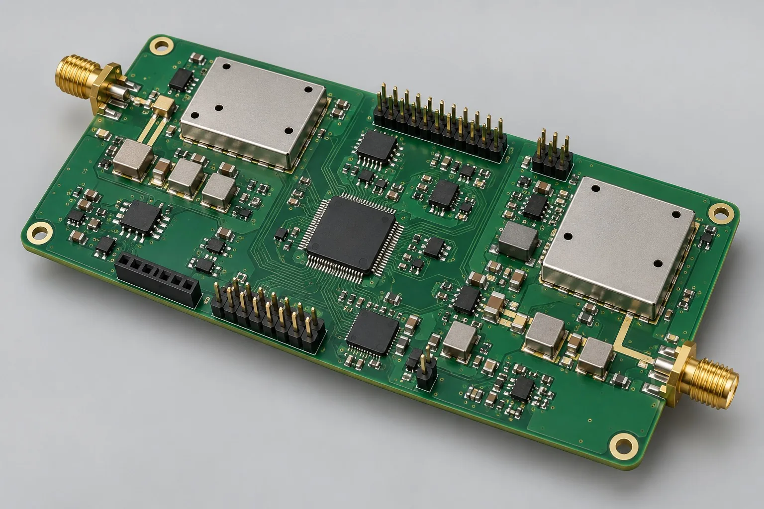
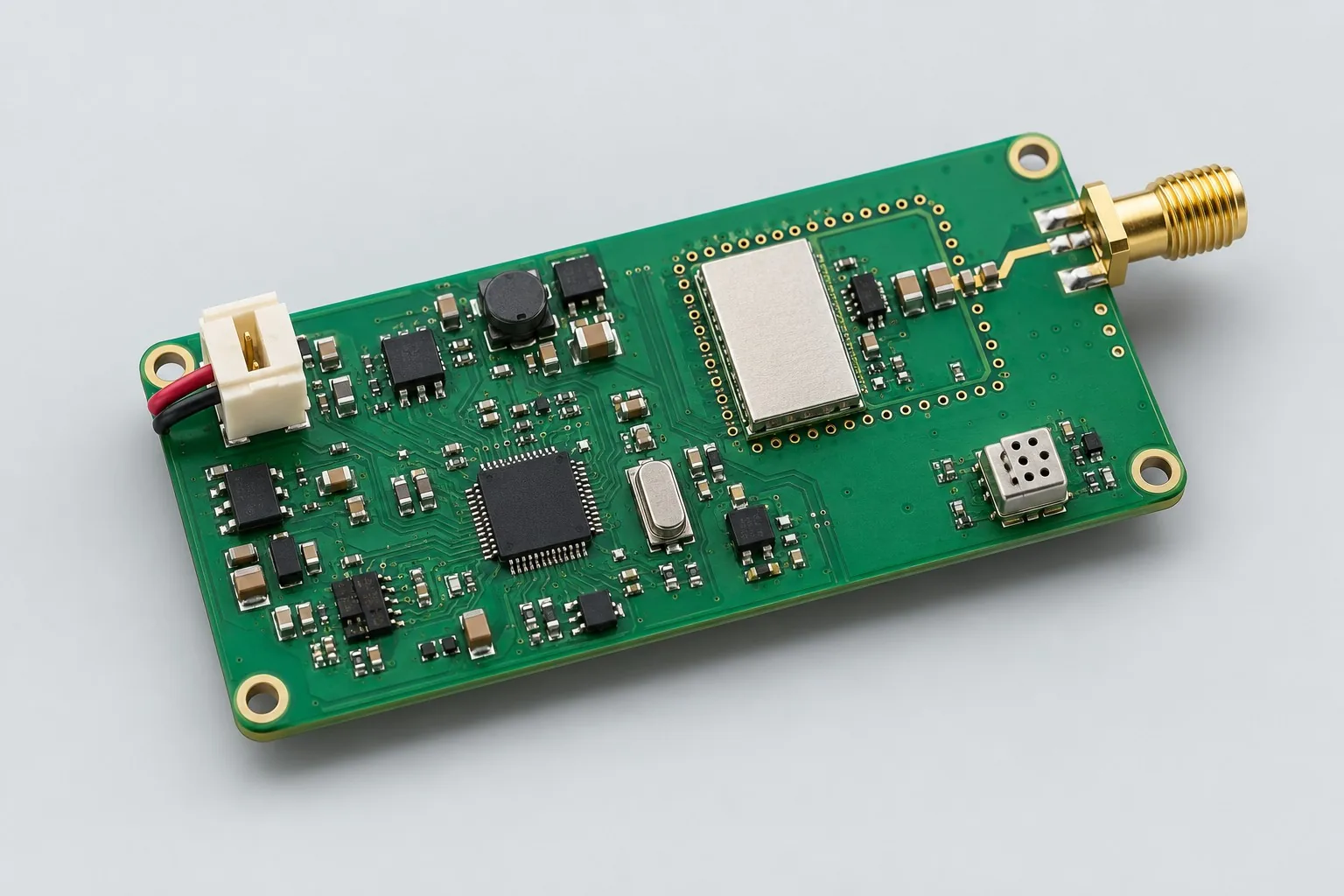
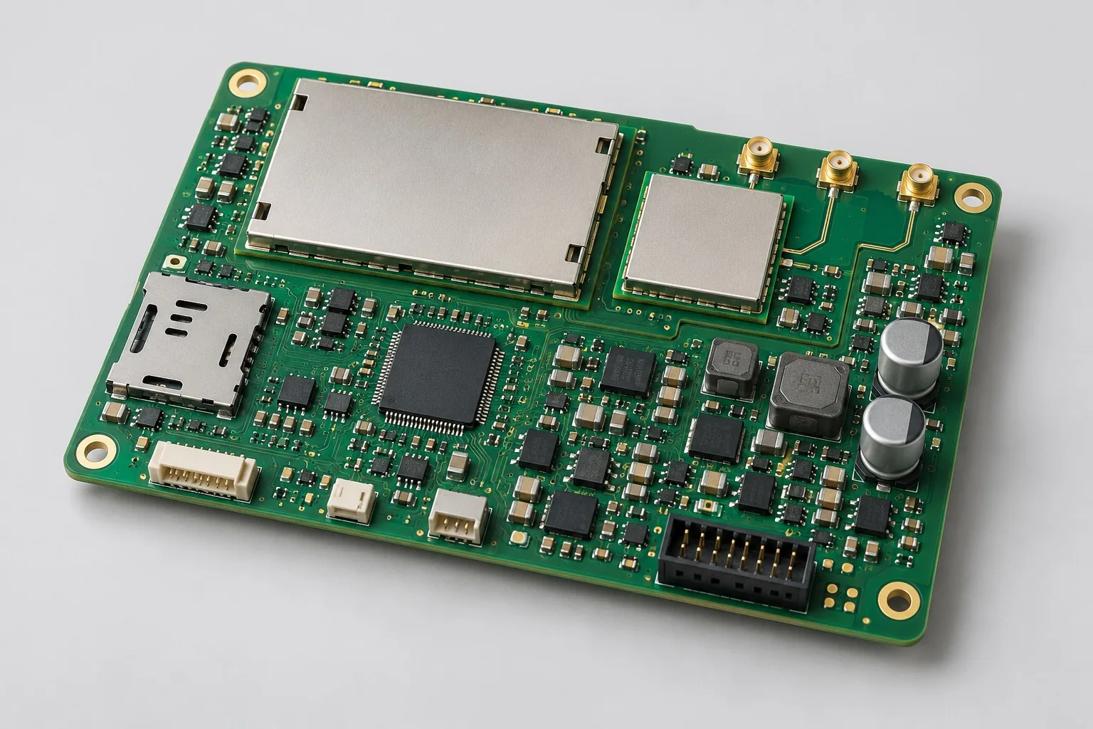
The 4G positioning mainboard serves terminals acquiring and remotely reporting locations: GNSS outputs data, the controller creates messages, and 4G uploads them; Bluetooth handles local configuration. Evaluate conventional multilayer construction first when outlines permit antenna spacing and debug access.
Custom development reference design. The following parameters are requirement configurations and design targets; validate functions and performance through agreed prototype tests.
| Functional Partition | Design and verification scope |
|---|---|
| Cellular / GNSS antenna | Confirm cellular/GNSS antenna types, mounting, and clearance separately; selected 4G modules define main/diversity ports, while active GNSS antennas also need bias power/protection. |
| Matching and RF Feedlines | Calculate feedlines using module ports/actual stackups and reserve matching adjustment; include connectors/coax lengths in loss budgets and reference planes in debug records. |
| 4G / GNSS module | Define GNSS protocols, 4G bands, and AT interfaces; read/upload positions periodically and separately agree on no-fix/no-network behavior. |
| Main Controller Data and SIM | The controller manages position messages, SIM status, and reporting intervals; define Bluetooth parameter permissions, retention, and recovery with firmware interfaces. |
| Peak Power Supply | Review charging, protection, and battery budgets for lithium versions and input protection/conversion for 12V external supply. Check module voltage at 4G transmit peaks separately for both. |
| Shielding/enclosure joint debugging | Check coexistence with enclosure, shields, and antenna mounting; separately record open-enclosure debugging differences and enclosed positioning/upload results. |
How much does 4G GPS positioning mainboard design cost, and how is it quoted?
Conventional 4G GPS mainboards allow antenna spacing/debug access; costs focus on peak power, fix states, and upload recovery. Compact HDI adds breakout/mechanical adaptation. Freeze enclosures, antennas, and reporting cadence before comparing firmware, prototypes, testing, and application-platform costs.
Quotation terms depend on the approved files, quantity, material supply, tests and delivery requirements.
Prepare a structured RFQ or use the short inquiry form.
| Quotation Items | What services are included | What to Check When Comparing Quotes |
|---|---|---|
| Circuit and PCB Design | Conventional multilayer GNSS/4G layout, power transients | Reusable portions of existing designs and circuit/mechanical changes |
| Software and Validation | Antenna installation and message upload | Price board-side GNSS/4G separately from maps, SIMs, and servers |
| Prototype Preparation | Bare PCB, BOM procurement, assembly, and agreed prototype quantity | Whether material/component revisions, prototype quantities, and test targets match |
| Subsequent Revision | Record new requirements separately from post-test corrections | How agreed changes, source files, and validation results are delivered |
How should conventional 4G GPS mainboards and compact HDI trackers be selected?
Where enclosures permit, conventional multilayer boards retain antenna spacing/debug positions; compare HDI for extreme compactness. Check size, antennas, and battery separately rather than board price alone.
Are internal or external antennas better for 4G positioning mainboards?
Compare mounting, enclosure materials, feedline length, and maintenance. Both need complete-unit validation at actual positions; 50Ω feedlines alone do not guarantee satellite acquisition or communication.
Do positioning-mainboard design quotations include maps and SIM costs?
Price board-side GNSS/4G separately from maps, SIMs, and servers. For customer platforms, agree on messages/access testing; board development does not automatically include ongoing network operations.
Reference configuration: GNSS positioning and 4G upload
| Configuration Field | Reference Configurations/Selections | Basis and Status |
|---|---|---|
| Reference application | GNSS positioning and cellular reporting with local Bluetooth configuration | Illustrative configuration; prototype validation required |
| Finished Product Function | Positioning, cellular upload, and near-field configuration | Design Objective |
| Cellular Architecture | Complete 4G module + SIM + main/diversity antenna options | Design Objective |
| Positioning Architecture | GNSS module + active/passive antenna options | Design Objective |
| Bluetooth Architecture | Bluetooth module or Bluetooth-capable controller for local configuration | Design Objective |
| Power Supply Objective | Single-cell lithium or 12V external supply options | Design Objective |
| RF Network | Module supply by manual; antenna-feedline 50Ω target | Design Objective |
| Interface Configuration | UART positioning/AT, USB debugging, charging port | Design Objective |
| Stackup Candidate | 4–6-layer through-hole construction; retain RF references first | Design Objective |
| Antenna Location | Separate matching/keepouts for main antenna, GNSS, and Bluetooth | Design Objective |
| Protection Configuration | ESD design for SIM/USB/external antennas | Design Objective |
| Validation outputs | S-parameters, receive/transmit coexistence, complete-unit coverage records | Design Objective |
Comparison of conventional multi-layer layout and compact solution
This page starts with 4G positioning requirements or existing schematics, customizing control, positioning, communication, power, and layout. Compared with compact HDI, conventional multilayer construction prioritizes antenna spacing, debug space, and through-holes. Breakout/mechanical review still determines whether 4–6 layers apply.
Cellular main/diversity antenna requirements vary by module; retain port definitions from module hardware guides.
External power reduces battery constraints but still requires automotive/industrial transient assessment.
Design budget and trade-off examples
Check design targets with engineering calculations
If feedline, connector, and adapter losses are 0.6, 0.2, and 0.3dB, total loss is 1.1dB, giving power ratio 10^(−1.1/10)≈0.776.
Conditions and Scope of Application:This calculates transmission-path loss only; add antenna mismatch, enclosure, receiver noise, and propagation separately. It cannot promise communication range.
Replace example assumptions with actual components, loads, and mechanics before work, retaining inputs, calculations, margins, and corresponding measurements. Budgets reveal bottlenecks; acceptance comes from that revision's prototype records.
Power and layout for GNSS positioning and 4G upload
- Keep RF-pad-to-antenna transitions short, placing matching near the adjusted element and identifying revisions.
- Separate GNSS front ends from cellular transmission, inductors, and clocks; add ground vias along paths and review shields.
- Follow manuals for module grounding/thermal paths; model antenna clearance with enclosures.
Positioning mainboard design inputs
- Functions, positioning/reporting intervals, server messages; selected-module guides, bands, antenna data
- Outline, mounting holes, enclosure/antenna three-dimensional positions; feedline/coax lengths and connections
- Use scenarios, lithium/external supply, Bluetooth configuration, and simultaneous positioning/upload needs
For existing designs, provide editable schematics, PCB, BOM, and issues to commission interface review, layout revisions, or prototype integration. With functions only, confirm specifications before selection/schematics. Agree separately on platform development, Bluetooth tools, and firmware scope.
Positioning mainboard phase deliverables
| Stage | Engineering Work for This Proposal | Reviewable Deliverables |
|---|---|---|
| Requirements and Design Freeze | Map positioning-to-upload data, intervals, configuration access, outlines/antennas; separate lithium/external supply needs | Requirements specification, interface/protocol list, mechanical constraints, open items |
| Schematic and Component Selection | Complete controller, GNSS, 4G, and Bluetooth configuration circuits; confirm SIM, debug, power tree, and RF ports | Editable schematics, BOM, footprint checks, design calculations |
| Layout and Routing | Implement feedline impedance, references, antenna clearance, and power-return constraints; check outlines/assembly interference | PCB sources, stackup, critical constraints, DRC, mechanical checks |
| Simulation/Calculation | Band matching and feedline/coexistence budgets; RF simulation and complete-unit antenna tests as needed | Models/inputs, analysis, assumption boundaries; calculations do not replace measurements |
| Prototype and Software | Build prototypes from frozen fabrication files and integrate agreed GNSS readout, 4G reporting, and Bluetooth firmware | Gerber, drill files, assembly drawings, and pick-and-place files/CPL; revision-marked prototypes, agreed firmware, programming/recovery instructions, configuration-interface documentation |
| Testing and Version Closure | Test positioning, message upload, Bluetooth parameter retention, and fault recovery, linked to RF/power checks | Test software, fixture interfaces, raw records, issue/revision lists; final performance comes only from that revision's report |
Positioning mainboard prototype verification
- Board feedline/matching S-parameters and connector checks
- GNSS signal-to-noise/fix stability during transmission
- Complete-unit antenna efficiency or controlled comparative alternatives
- ESD prechecks, weak-signal retries, extended thermal records
Prototype acceptance first checks GNSS fixes, controller messages, server receipt of 4G data, and Bluetooth parameter retention/recovery. Then test no-fix, network reconnection, and transmit power under agreed scenarios; reports identify equipment, revisions, environments, and criteria.
Locator main board prototype verification worksheet
The worksheet below defines RF/whole-board integration acceptance methods. Set positioning errors, report-success criteria, and recovery deadlines from use scenarios and enter them in requirements revisions; the table is a validation plan.
| Verification Object | Pre-Production Freeze | How to Test Prototypes in Practice | Delivery and Acceptance Records |
|---|---|---|---|
| RF Path | Cellular/GNSS modules, antennas/harnesses, measurement reference planes | Measure board feedline S-parameters and inspect installed enclosure/antenna conditions | Deliver port drawings, matching BOM, raw data; separate feedline performance from complete-unit antenna efficiency |
| Transmit Receive Coexistence | Valid-fix conditions, 4G reporting intervals, message formats, server-receipt criteria | Compare GNSS with cellular off/transmitting and check server messages against controller position data | Retain positioning/upload/receipt logs and concurrency conditions, distinguishing data-path errors, coupling, and external obstruction |
| Weak Signal Thermal and Power | Supply input, retry strategy, ambient temperature, thermal limits | Fix network attenuation or field conditions and run reporting/retries | Record retries, module voltage, temperature rise; identify conditions rather than claiming generic communication range |
Manufacturing and assembly coordination for this design
- Prevent post-reflow mechanical damage at shield pads, antenna sockets, and coax fasteners.
- Include RF fixture alignment/calibration planes in test plans; retest antenna changes.
Link design revisions to schematics, BOM, PCB, fabrication, and software documentation. When fabricators adjust stackup, materials, or holes, or Assembly parties propose substitutions, recheck critical electrical and test conditions together.
Assembly and testing configuration for this functional board: tracker PCB assembly and testing configuration. Design covers source files, component selection, and validation targets; PCB assembly sources/receives materials, assembles, programs agreed files, and performs production tests against approved BOMs. This link opens a production configuration for the functional area; it does not mean both pages share a physical model.
Common questions on purchasing and customization
How much does 4G GPS positioning mainboard design cost, and how is it quoted?
A project-specific quotation requires review of the available files, quantity, materials, requested tests, delivery destination, taxes, shipping, and trade terms. Any formula on this page organizes cost inputs; it is not a quoted rate.View cost items, calculation conditions, and sources.
Does replacing a 4G positioning-board antenna require software changes?
Check bands, connections, power, and installation first; software changes depend on positioning/network state handling. Regress RF and upload in all cases.
How should positioning-mainboard prototype acceptance scenarios be selected?
Define open, obstructed, weak-signal, and network-loss scenarios from actual installation, retaining tracks/report logs rather than judging whole boards by one fix.
How should conventional positioning-mainboard budgets compare power approaches?
List input, transients, and state machines separately for single-cell lithium charging and 12V external supply, retaining equal GNSS/4G/Bluetooth protocol scope. Conventional 4–6 layers retain debug access; specify antenna installation, satellite acquisition, and deferred-upload prototypes rather than applying battery-terminal budgets directly to fixed externally powered equipment.
Can RF layout alone deliver a functioning positioning service?
50Ω feedlines, three antenna positions, and references are hardware tasks only. GNSS parsing, AT control, timestamps, acknowledgments, and recovery need firmware; maps/servers are other endpoints. Accept service operation separately from RF-board manufacturability.
How can existing customer platforms reduce duplicated positioning development?
Provide messages, authentication, acknowledgments, and buffering rules to avoid another server interface. Boards still need fix-state/network-loss adaptation and actual-platform upload, retransmission, and deduplication records. Separate SIM/ongoing service costs from one-time engineering.
Which antenna/debug documentation should positioning mainboards deliver?
Agree on feedlines, connectors, antenna models/positions, matching BOMs, and S-parameter planes, linked to actual enclosure installation. Firmware includes AT/position logs, upload protocols, and recovery tools so antenna/module replacements can regress under identical conditions rather than retaining one track screenshot.
How should replacing internal antennas with external antennas be treated as a design change?
Check feedline length, connector ESD, enclosure openings, active-GNSS power, and mounting direction to define layout/mechanical changes. Software depends on module state handling, but regress reception/upload for both installations; connector-price differences alone are insufficient.
Can one positioning board be used directly in any vehicle or equipment?
Check supply fluctuations, grounding, antenna positions, and actual environments before defining interfaces/protection. Position messages may be reusable, but adapt external power and complete-unit coverage validation. Arrange environmental validation separately for this installation.
How should I prepare an RFQ before commissioning 4G GPS positioning mainboard design?
Initially describe target functions, application, and existing files. Engineering quotations further confirm functions, positioning/reporting intervals, server messages; selected-module guides, bands, antenna data; outlines, mounting holes, enclosure/antenna three-dimensional positions, feedline/coax lengths/connections; use scenarios, lithium/external power, Bluetooth configuration, and simultaneous positioning/upload. Provide editable schematics, PCB, and BOM for existing circuits, and revisions/reproduction records for faulty prototypes. List documentation gaps as review tasks so quotations do not use different assumptions.
How should 4G GPS positioning-mainboard prototype validation costs be compared by operating condition?
Freeze prototype quantity, revision, equipment, and criteria sources first. For RF paths, freeze modules, antennas/harnesses, and planes; measure board S-parameters and inspect installed conditions. For coexistence, freeze valid-fix conditions and 4G reporting intervals, formats, and server criteria; compare GNSS with cellular off/transmitting and server/controller data consistency. For weak-signal thermal/power tests, freeze supply, retries, ambient, and thermal limits; run reports/retries at fixed attenuation or field conditions. State whether raw data and issue closure are delivered; one power-on pass is not complete validation.
Compare related designs and plan the next step
Compact HDI positioning mainboard: compare battery space and breakout · Low-power Sub-GHz wireless sensor transceiver board design
Return to RF PCB design selection · Select solution by device function · Discuss your design requirements
Documentation Basis and Boundaries
Engineering reference | ESP32-S3 PCB layout: power, RF, and antenna clearance: reference only the actual ESP32-S3 Bluetooth-controller layout, not 4G/GNSS selection. Follow actual module hardware guides for cellular/positioning. This configuration and acceptance plan are illustrative engineering references; they do not establish a KFPCBA development or production history.