Engineering reference design · prototype validation pending
Sub-GHz design: sensor messages to base stations
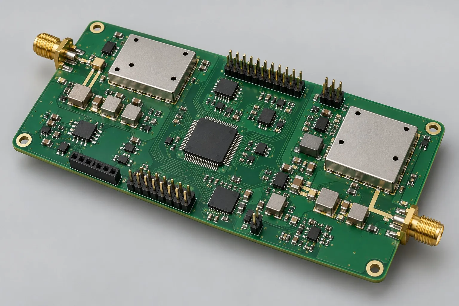
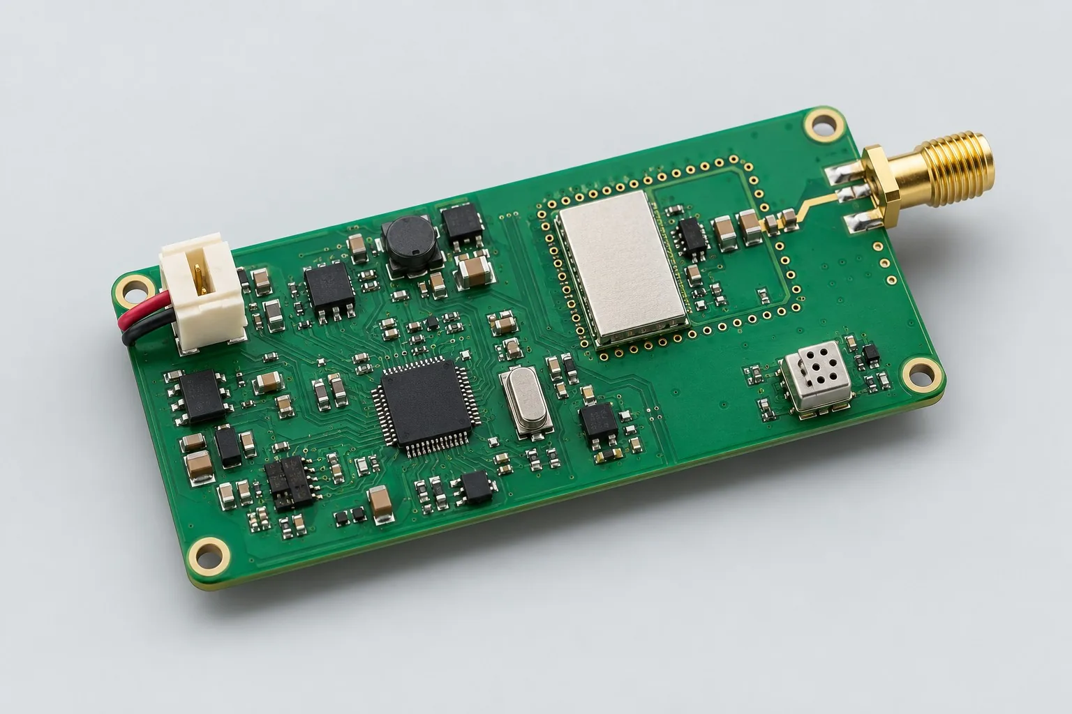
The Sub-GHz sensor transceiver board sends sensor messages between nodes and a base station over a single-band link. The controller manages periodic wake-up, transmit/receive windows, and limited retries. A 3.3V external supply is the basic approach; separately calculate sensing, receiving, and transmitting task charge for battery nodes.
Custom development reference design. The following parameters are requirement configurations and design targets; validate functions and performance through agreed prototype tests.
| Functional Partition | Design and Inspection Objects |
|---|---|
| Sub-GHz antenna port | Define the regional band, antenna, and enclosure clearance. The 433MHz requirement is an example and establishes neither permitted power nor range. |
| RF matching and transceiver | Configure matching, filtering, and crystals for CC1101-class transceivers/modules according to the selected band; retain the tuned BOM. |
| Low Power MCU | The MCU controls the transceiver through SPI and manages node IDs, sequence numbers, RSSI, and limited retries. |
| Sensor / Data Interface | Define I²C/ADC sensor inputs and UART maintenance separately; use comparison testing to check sensing deviations during transmission. |
| Battery Power | Review the basic 3.3V external-supply and battery approaches separately; measure current at transmit/receive peaks, during receive windows, and in sleep. |
| Wake-Up / Transmit-Receive Duty Cycle | Freeze wake-up/transmit/receive timing and acknowledgment/timeout strategies; weak-signal retries must not extend the operating duty cycle indefinitely. |
How much does Sub-GHz design cost, and how is it quoted?
Sub-GHz node costs depend on the band, messages, and base-station integration tasks. Reusing an existing base-station protocol differs from developing both ends from scratch; battery operation adds sleep, retries, and task-charge measurements. Distinguish matching/layout, node firmware, base-station work, and fixed-scenario link tests in the quotation instead of pricing by advertised range.
Quotation terms depend on the approved files, quantity, material supply, tests and delivery requirements.
Prepare a structured RFQ or use the short inquiry form.
| Quotation Items | What services are included | What to Check When Comparing Quotes |
|---|---|---|
| Circuit and PCB Design | Single-frequency matching, message, and task duty cycle | Reusable portions of existing designs and circuit/mechanical changes |
| Software and Validation | Packet error, retransmission, and current measurement | Node radio, station protocol, station hardware can be commissioned separately |
| Prototype Preparation | Bare PCB, BOM procurement, assembly, and agreed prototype quantity | Whether material/component revisions, prototype quantities, and test targets match |
| Subsequent Revision | Record new requirements separately from post-test corrections | How agreed changes, source files, and validation results are delivered |
How should single-band Sub-GHz and dual-band boards be selected?
Compare single-band operation for sensor messages alone; consider dual-band operation if mobile maintenance or a second link is needed. The latter adds antennas, coexistence work, and software, so additional features alone do not justify selection.
How should range and batteries be selected for 433MHz boards?
Freeze the regional band, antenna, scenario, and message period first, then measure packet errors and retries under fixed conditions. These conditions affect both range and battery life; neither a band label nor maximum chip power establishes either outcome directly.
Does Sub-GHz development include base stations?
Node transmit/receive functions, base-station protocols, and base-station hardware may be commissioned separately. Specify node count, acknowledgments/timeouts, logs, and fixed-scenario tests. Integrating an existing base station is different from developing one from scratch.
Reference: sensor messages to Sub-GHz stations
| Configuration Field | Reference Configurations/Selections | Basis and Status |
|---|---|---|
| R&D Direction | Sub-GHz sensor development reference | Illustrative design direction; requirements and prototype validation must be agreed |
| Reference Function | Wireless Sensor Message Transmission and Status Reporting | Design Objective |
| Frequency Band Example | 433MHz; confirm the actual band for the region | Design Objective |
| RF Candidate | CC1101 class transceiver or module | Design Objective |
| Power Supply Objective | 3.3V external supply; separate battery-node budget | Design Objective |
| Sensor Interface | I²C Plus 2 Channel ADC Requirement Example | Design Objective |
| Communication Structure | MCU SPI radio control, UART service | Design Objective |
| Message Mode | Example target: transmission every 60 seconds + event alarms | Design Objective |
| Stackup Candidate | 2 Layer / 4 Layer Compared by Power and Space | Design Objective |
| Antenna Configuration | External or PCB antenna, matching adjustment | Design Objective |
| Firmware Function | Wakeup, retries, sequence, node ID, RSSI logs | Design Objective |
| Verify Output | Packet-error rates, radio currents, frequency offset, precompliance tests | Design Objective |
Single-band link and task charge
A single-band, low-message-volume approach reduces coexistence complexity; add Bluetooth or select a dual-band approach if direct phone configuration is required.
Link transmit power to current, regulatory requirements, and battery budgets; maximum chip power is not the default configuration.
Limit node retries and define buffering strategies to prevent continuous power drain under weak signals.
Design budget and trade-off examples
Check design targets with engineering calculations
Transmitting 50ms every 60 seconds at 30mA contributes 30×0.05/60=0.025mA average; add receive/sensing/sleep separately.
Conditions and Scope of Application:This value illustrates power decomposition only and does not calculate communication range. Confirm the over-the-air protocol, receive windows, retransmissions, and regional band requirements.
Replace examples with selected components and record margins; calculations support design choices, while prototype records support acceptance.
Power/layout for sensor messages to Sub-GHz stations
- Check matching against the reference circuit for the selected band; place the crystal and decoupling close to the transceiver.
- Maintain mechanical antenna clearance from the battery and metal enclosure; freeze layout after mechanical approval.
- Keep ADC sensing areas away from RF outputs; provide separate access for operating-current measurement and RF probing.
Sub-GHz Node Development Input
- Region, channel, message volume, distance scenarios
- Antenna/enclosure, power, sensor types
- Retries, wakeup, node counts, station protocol
If circuit files exist, provide editable schematics, PCB, BOM, and current issues, and agree on review or revision scope. If only functions are defined, freeze this page's inputs before selection and circuit development. Agree separately on control-software and external-application responsibilities, interfaces, and acceptance.
Sub-GHz Node Phase Deliverables
| phase | Engineering Work for This Proposal | Reviewable Deliverables |
|---|---|---|
| Requirements and Design Freeze | Freeze regions/channels/messages, node/station protocols, power approaches | Functional/interface requirements, mechanical revision, acceptance conditions, and open items |
| Schematic and Component Selection | Design the transceiver, matching, controller sensor interfaces, and power-domain enables | Editable schematics, controlled BOM, footprint checks, and design calculations for these circuits |
| Layout and Routing | Complete antenna, crystal, decoupling, and ADC partitioning; preserve access for RF and current tests | PCB source files, actual stackup/hole/net constraints, DRC, and assembly-dimension checks |
| Simulation/Calculation | Budget airtime, receive windows, retries, charge; set queue limits | Design calculations/models, input conditions, margins, and items awaiting measurement |
| Prototype and Software | Build single-band prototypes; integrate sampling/wakeup/sequence acknowledgments/retries/RSSI | Manufacturing package, Sub-GHz transceiver prototype, agreed node/base-station firmware, messages/timing, matching BOM, and recovery instructions |
| Testing and Version Closure | Measure packet errors/retransmissions in fixed scenarios; check task charge and transmission effects on sampling | Procedures, wiring, raw results, and decisions for the prototype revision; include issue/change and limitation lists |
Single-band packet-error and power verification
- Packet-error statistics at fixed scenarios/distances/interference
- Transmit/receive/standby current and period budgets
- Frequency offset, RF output, and spurious pre-check
- Sampling interference/recovery during transmission
Measure packet errors/retries in fixed scenarios, checking task charge and the effect of transmission on sampling. Document equipment, conditions, revisions, and acceptance criteria in the report, including passed items and untested conditions.
Single-band packet-error and power verification worksheet
The table below breaks sensor messaging to a Sub-GHz base station into actionable checks. Freeze samples, equipment, environment, and allowable deviations before testing; link results to this revision’s raw records.
| Verification Object | Pre-Production Freeze | How to Test Prototypes in Practice | Delivery and Acceptance Records |
|---|---|---|---|
| Link Scenario | Regional bands, antenna, packet length, distance, retry rules | Fix location/orientation/interference and count transmitted/received sequences | Deliver total packet counts, packet-error rates, and retransmissions, beyond a single maximum-distance trial |
| Task Charge | Message period, wake time, supply/battery conditions | Measure sensor, transmit, receive-window, sleep currents | Integrate task charge and list battery-life assumptions; distinguish the basic externally powered version from the battery version |
| Sampling Coexistence | Sensor types, power domains, permitted noise | Compare sampling with transmitter off/on | Retain offset/noise and supply waveforms; determine whether time-separated operation is needed according to sensing requirements |
Manufacturing and assembly coordination for this design
- Maintain separate revisions for the tuning and production BOMs; do not arbitrarily change antenna materials or lengths.
- Use a shielded environment and fixed coupling in the fixture; distinguish production test results from free-space range.
Link design revisions to schematics, BOM, PCB, fabrication, and software documentation. When fabricators adjust stackup, materials, or holes, or Assembly parties propose substitutions, recheck critical electrical and test conditions together.
Compare mobile communication module RF assembly processes. This page’s Sub-GHz sensor-messaging design is not equivalent to the linked mobile communication module. Compare responsibility divisions for RF assembly, grounding, and port testing, but do not transfer its bands, amplification chain, or acceptance parameters. This design still needs its own BOM, manufacturing package, firmware, and communication test plan for production.
Common questions on purchasing and customization
How much does Sub-GHz design cost, and how is it quoted?
A project-specific quotation requires review of the available files, quantity, materials, requested tests, delivery destination, taxes, shipping, and trade terms. Complete development separately prices circuits, firmware, prototypes, and verification. Any formula on this page organizes cost inputs; it is not a quoted rate.View cost items, calculation conditions, and sources.
How should single-band Sub-GHz and dual-band boards be selected?
Compare single-band operation for sensor messages alone; consider dual-band operation if mobile maintenance or a second link is needed. The latter adds antennas, coexistence work, and software, so additional features alone do not justify selection.
How should range and batteries be selected for 433MHz boards?
Freeze the regional band, antenna, scenario, and message period first, then measure packet errors and retries under fixed conditions. These conditions affect both range and battery life; neither a band label nor maximum chip power establishes either outcome directly.
Does Sub-GHz development include base stations?
Node transmit/receive functions, base-station protocols, and base-station hardware may be commissioned separately. Specify node count, acknowledgments/timeouts, logs, and fixed-scenario tests. Integrating an existing base station is different from developing one from scratch.
How should Sub-GHz packet-error rates be compared?
Fix the scenario, orientation, antenna, message length, and retry rules; count total packets and errors rather than comparing only a single maximum-range trial.
Do more wireless retries always improve reliability?
Retries increase task time and charge. Limit timeouts and buffering together, comparing data availability and battery budgets instead of extending transmission indefinitely.
How should single-band budgets separate nodes and stations?
The node package lists CC1101-class matching, sensor inputs, and wake-up/transmit/receive functions; list existing-base-station integration or a new base station separately. Keep acknowledgment, retry, and charge tests for the every-60-second message example under the same conditions. An existing base-station protocol can reduce development, but advertised maximum range cannot determine pricing.
Which frequency information is needed for Sub-GHz layout only?
Provide the actual regional band, selected transceiver reference, matching/antenna, enclosure, and 3.3V supply; define crystal and sensing partitions. Layout implements RF and ADC return paths. Undefined messages, retries, or receive windows require additional protocol work; the 433MHz example establishes neither regional authorization nor complete-board performance.
Which parts of node firmware still need development when a base station already exists?
Confirm frame length, node ID, sequence numbers, acknowledgments/timeouts, buffering, and event-alarm rules. Keeping the base station can reduce central-side development, but node drivers, wake-up behavior, and weak-signal retry charge still require measurement. One successful connection does not replace lost/duplicate-packet or battery tests.
Which wireless parameters should accompany single-band node source code?
Deliver the matching BOM, crystal/band settings, SPI control, and power-domain design. Include message periods, receive windows, retry limits, and RSSI logs with firmware. Retain fixed antenna/orientation scenarios and task-current records so later reporting-rate or enclosure changes can be recalculated from original data.
How should the development scope be requoted when an externally powered node becomes battery powered?
Review regulation/load switches, sleep, and sensor power-up; integrate task charge over transmission, receive windows, and sleep. The message protocol may be reusable, but weak-signal retries and low-battery recovery require regression testing. Battery capacity alone does not justify carrying over operating conclusions from the externally powered version.
Can single-band sensor nodes directly add phone maintenance?
An ordinary phone cannot connect directly merely because a 433MHz node exists. Add Bluetooth/Wi-Fi or specify an external gateway separately. The sensor protocol may remain, but list the second link, antenna, coexistence, and maintenance software separately. This page’s basic single-band budget excludes a dual-band system.
How should I prepare a Sub-GHz design RFQ?
Start with the target functions, application, and available files. An engineering quotation then confirms region, channels, message volume, and range scenarios; antenna/enclosure, supply, and sensor types; and retries, wake-up, node count, and base-station protocol. For an existing circuit, provide editable schematics, PCB files, and BOM. For a faulty prototype, include its revision and reproduction records. List missing information as review tasks so both parties quote against the same assumptions.
How should Sub-GHz wireless board prototype verification costs be compared by operating condition?
Fix the prototype quantity, revision, equipment, and source of acceptance criteria before comparing costs. Check at least these areas separately: link scenarios—freeze regional band, antenna, packet length, distance, and retry rules, then count transmitted/received packet sequences at fixed positions/orientations and interference conditions; task charge—freeze message period, wake-up time, and supply/battery conditions, then measure sensing, transmission, receive-window, and sleep currents; sampling coexistence—freeze sensor type, supply domains, and allowable noise, then compare samples with transmission off and on. State whether raw data and issue closure are included; one successful power-on does not constitute complete verification.
Compare related designs and plan the next step
4G positioning terminal RF mainboard design · Sub-GHz and 2.4GHz dual-band communication board design
Return to RF PCB design selection · Select solution by device function · Consult This Proposal R&D Team
Chinese-language documentation | CC1101 reference: selection conditions and board-level verification: CC1101 documentation is a reference for the component’s bands, matching, and control; confirm regional authorization, board-level packet errors, and battery life in actual scenarios.