Engineering reference design · prototype validation pending
Dual-band communication board design: Sub-GHz sensing and 2.4GHz configuration
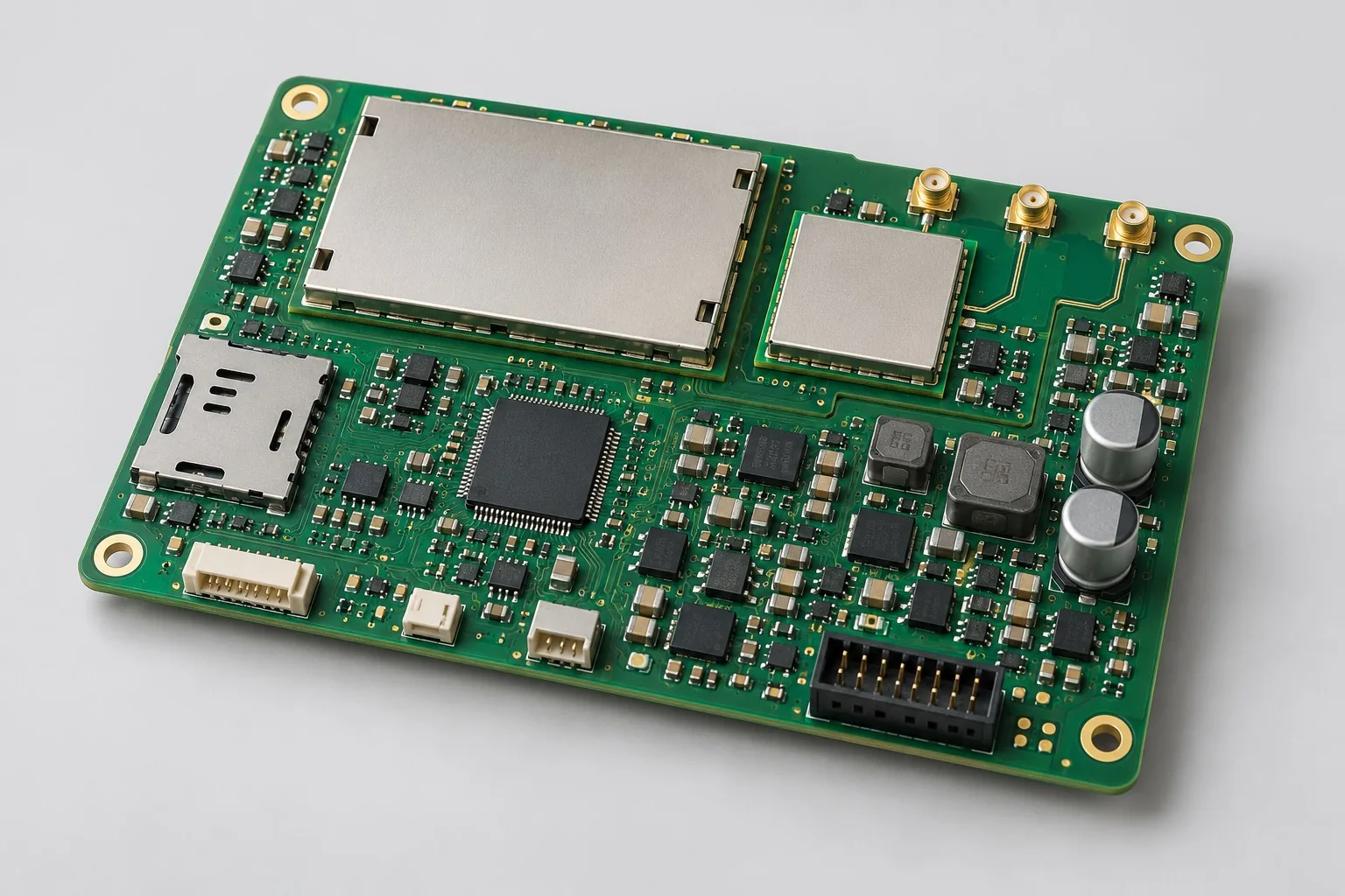
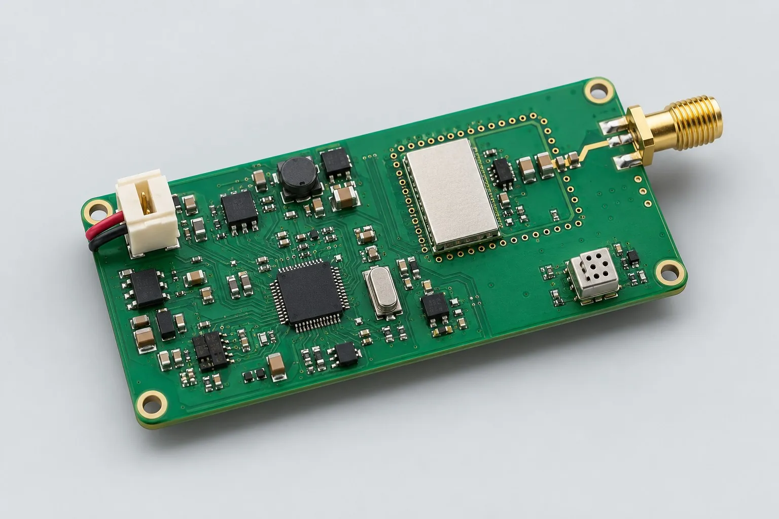
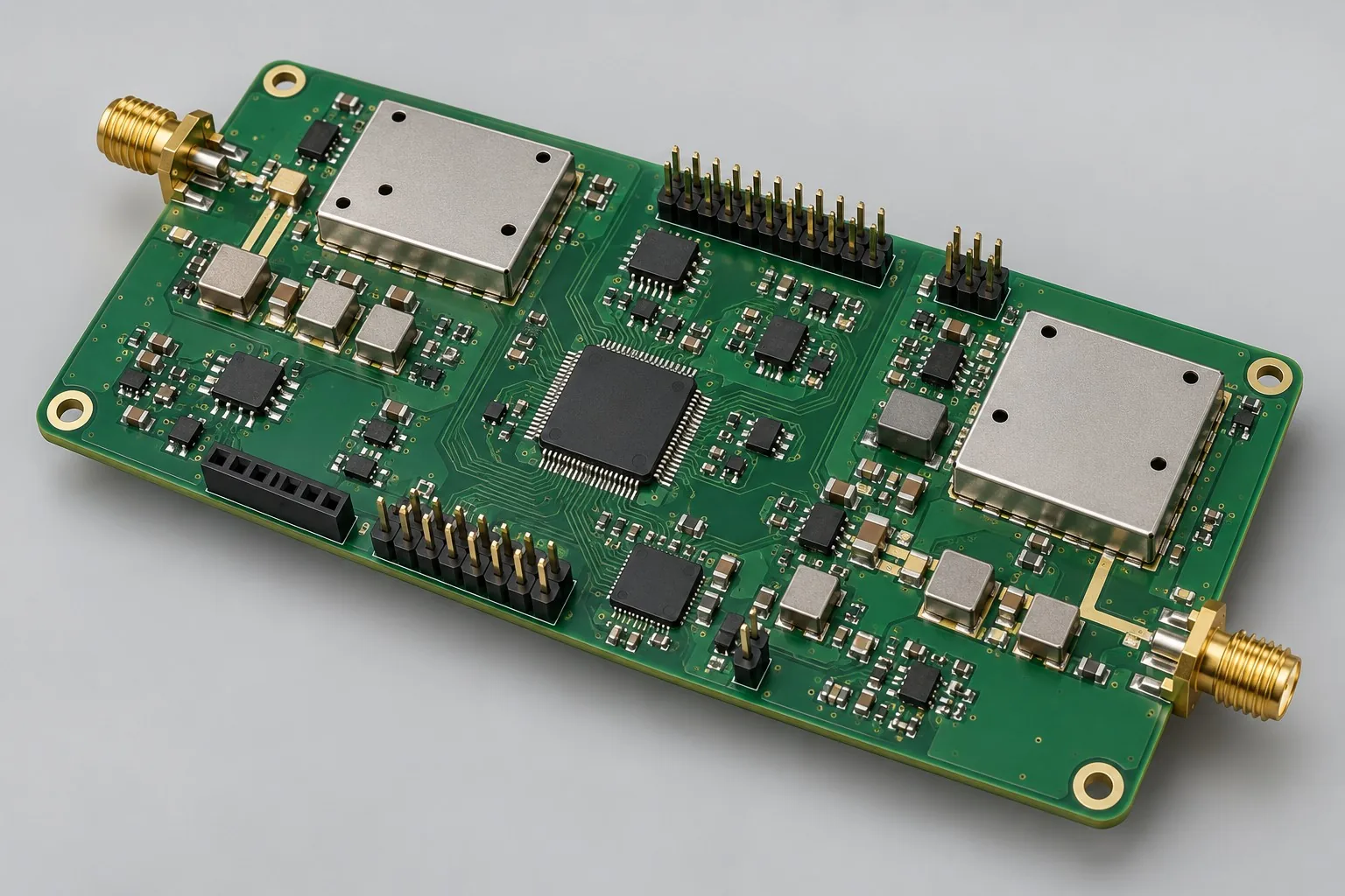
Dual-band communication boards use Sub-GHz for field sensor packets and 2.4GHz for nearby maintenance/configuration. The controller independently manages both transceivers; review antenna coupling, power, and queue recovery for simultaneous or time-divided operation.
Custom development reference design. The following parameters are requirement configurations and design targets; validate functions and performance through agreed prototype tests.
| Functional Partition | Design and verification scope |
|---|---|
| Dual-Band Antenna Ports | Freeze each Sub-GHz and 2.4GHz band, antenna, and enclosure position; measure port coupling in actual structures. |
| Independent Matching and Filtering | Design matching/filtering separately for each device and band; do not reuse component values across bands. |
| Dual-Band Transceiver | CC1101-type transceivers/modules handle Sub-GHz; select Bluetooth/Wi-Fi devices separately by maintenance protocol. Do not assume one chip supports both links. |
| MCU Protocol and Interface | The MCU manages packets/configuration through SPI/UART and independent interrupts; define chip selects, concurrent timing, and buffers. |
| Partitioned Power Supply | Separately enable and measure current in 5V-to-3.3V wireless domains, capturing voltage drops and receive noise during dual transmission. |
| Coexistence/switching test | Compare single/dual-link packet-error rates, desensitization, and latency; define scenarios requiring time division and queue-discard rules. |
How much does dual-band wireless board design cost, and how is it quoted?
Itemize both links and coexistence work. Reusable single-band messaging, added 2.4GHz maintenance protocols/antennas, and simultaneous-operation requirements affect development. List nodes, base stations, and mobile clients as separate endpoints; two radio component prices do not establish a dual-band system development budget.
Quotation terms depend on the approved files, quantity, material supply, tests and delivery requirements.
Prepare a structured RFQ or use the short inquiry form.
| Quotation Items | What services are included | What to Check When Comparing Quotes |
|---|---|---|
| Circuit and PCB Design | Coexistence of two RF links, antennas, and power supplies | Reusable portions of existing designs and circuit/mechanical changes |
| Software and Validation | Sensor message and maintenance protocol | Itemize node dual-band management, packet formats, and maintenance protocols; list new base-station/mobile development separately |
| Prototype Preparation | Bare PCB, BOM procurement, assembly, and agreed prototype quantity | Whether material/component revisions, prototype quantities, and test targets match |
| Subsequent Revision | Record new requirements separately from post-test corrections | How agreed changes, source files, and validation results are delivered |
How do dual-band wireless boards differ from single-band Sub-GHz boards?
Single-band suits one sensor-message task. Adding 2.4GHz maintenance changes configuration methods but adds antenna, coexistence, and firmware work. Nearby mobile maintenance requirements determine the second link's value.
Can both links on dual-band wireless boards operate simultaneously?
Define transmit, receive, and configuration states, then test mutual interference and power. Dual-band devices do not establish unconditional simultaneous transmission/reception; stagger tasks when needed and retain verification records.
Do dual-band board quotations include both firmware sets and base stations?
Itemize node dual-band management, packet formats, and maintenance protocols; list new base-station/mobile development separately. Compare totals with identical endpoint counts and software scope.
Reference configuration for Sub-GHz sensing and 2.4GHz configuration
| Configuration Field | Reference Configurations/Selections | Basis and Status |
|---|---|---|
| Reference application | Sub-GHz sensor messaging with a separate 2.4 GHz maintenance link | Illustrative configuration; prototype validation required |
| Reference Function | Remote sensor data plus near-field configuration | Design Objective |
| RF Channel | 1 Sub-GHz link + 1 2.4GHz link | Design Objective |
| Band Target | 433MHz Sub-GHz example; deployment region requires confirmation | Design Objective |
| Sub-GHz candidate | CC1101 class transceiver or module | Design Objective |
| 2.4GHz Candidate | Bluetooth/Wi-Fi modules selected by link | Design Objective |
| Control Interface | MCU SPI + UART, independent chip selects/interrupts | Design Objective |
| Power Supply Objective | 5V input to 3.3V domain power supply | Design Objective |
| Antenna Structure | Two independent 50 Ω feed lines and matching | Design Objective |
| Stackup Candidate | 4-layer FR-4, RF layer adjacent to ground plane | Design Objective |
| Software Function | Channel configuration, transmit/receive queues, link status | Design Objective |
| Validation outputs | Transmit/receive sensitivity/frequency offset, coexistence, and airtime scheduling plan | Design Objective |
Dual-band concurrent and time-division scheduling
Using a module for each link reduces the first-revision RF development scope; bare-IC implementation requires additional matching and crystal debugging.
Coexistence may use time division or simultaneous operation; record required concurrency before selecting shielding.
Design transmit bands, power, and protocols for sales-region requirements; do not claim communication range without testing.
Design budget and trade-off examples
Check design targets with engineering calculations
Assuming each of two bands sends 10 frames per second at 32 bytes per frame, payload is 2×10×32=640B/s; add protocol headers, over-the-air encoding, and retransmissions separately.
Conditions and Scope of Application:Payload alone cannot determine airtime. Review power, duty cycle, coexistence, and regional band requirements separately for both RF paths.
Replace examples with selected components and record margins; calculations support design choices, while prototype records support acceptance.
Power and layout for Sub-GHz sensing and 2.4GHz configuration
- Check Sub-GHz matching against manufacturer reference designs for the selected band; do not copy values directly across bands.
- Separate both antennas and feedlines; keep control clocks away from high-sensitivity receiver inputs.
- Reserve enables, current measurement points, shielding cans, and RF test access for each wireless domain.
Dual-band communication board development input
- Deployment region, channel bandwidth, permitted transmit modes
- Target link range, packet size, and interval
- Dual-link concurrency conditions, enclosure, and antenna positions
If circuit files exist, provide editable schematics, PCB, BOM, and current issues, and agree on review or revision scope. If only functions are defined, freeze this page's inputs before selection and circuit development. Agree separately on control-software and external-application responsibilities, interfaces, and acceptance.
Dual-band communication board phase delivery
| Stage | Engineering Work for This Proposal | Reviewable Deliverables |
|---|---|---|
| Requirements and Design Freeze | Freeze deployment regions, both protocols, packet rates, and concurrency/antenna structures | Functional/interface requirements, mechanical revision, acceptance conditions, and open items |
| Schematic and Component Selection | Design both transceivers, matching filters, controller interfaces, and separate power domains | Editable schematics, controlled BOM, footprint checks, and design calculations for these circuits |
| Layout and Routing | Arrange dual-antenna feedlines, shielding, and clock return paths; retain separate RF measurement access | PCB source files, actual stackup/hole/net constraints, DRC, and assembly-dimension checks |
| Simulation/Calculation | Establish dual-link airtime, retransmission, coupling, and power budgets | Design calculations/models, input conditions, margins, and items awaiting measurement |
| Prototype and Software | Build dual-band prototypes and integrate channels, packet queues, maintenance configuration, and concurrent scheduling | Manufacturing package, dual-band prototypes, agreed protocol firmware, queue/configuration interfaces, and programming/recovery instructions |
| Testing and Version Closure | Test each transceiver link, then verify dual-link coexistence, congestion recovery, and enclosure/antenna coupling | Procedures, wiring, raw results, and decisions for the prototype revision; include issue/change and limitation lists |
Dual-band coexistence and queue recovery verification
- Single-link transmit/receive, frequency-offset, and operating-voltage tests
- Packet-error rates and receiver desensitization during simultaneous dual-link operation
- Retransmission and queue recovery under interference/disconnection
- RF output, spurious-emission, and precompliance test plan
Test each transceiver link, then verify dual-link coexistence, congestion recovery, and enclosure/antenna coupling. Reports specify equipment, conditions, revisions, and criteria, recording passed and uncovered items.
Dual-band coexistence and queue-recovery verification worksheet
The following table converts Sub-GHz sensing and 2.4GHz configuration into executable checks. Freeze samples, equipment, environments, and allowable deviations before execution; link results to this revision's raw records.
| Verification Object | Pre-Production Freeze | How to Test Prototypes in Practice | Delivery and Acceptance Records |
|---|---|---|---|
| Band and Concurrent Operation | Both links' regions/bands, power, packet rates, and concurrency strategy | Test one link, enable the other, and repeat identical interference conditions | Record packet-error rates, receiver desensitization, and queue latency; identify conditions requiring time division |
| Antenna Isolation | Both antenna positions, enclosure, and port reference planes | Measure port coupling in frozen structures and compare orientations | Deliver structural photos/position drawings and coupling data; reverify after enclosure changes |
| Queue Recovery | Message acknowledgments, maximum retries, and buffer-discard rules | Disconnect remote endpoints, inject congestion, then restore both links | Deliver sequence-number/retransmission logs; check duplicate and expired-message handling |
Manufacturing and assembly coordination for this design
- Do not arbitrarily consolidate/substitute small RF resistor/capacitor part numbers or packages; retain separate matching-tuning BOM revisions.
- Retain antenna mounting, shield, ground-via and assembly requirements in the controlled manufacturing revision.
Link design revisions to schematics, BOM, PCB, fabrication, and software documentation. Recheck critical electrical and test conditions when fabricators adjust stackup, materials, or holes or assemblers propose substitutes.
Compare cellular RF module assembly and testing boundaries. This dual-band sensor-messaging design differs from the linked multiband cellular module in bands, signal chains, and verification objects. The link is only a related RF assembly-process reference; it does not establish circuit equivalence or corresponding production models. Define this project's RF specifications and production tests separately.
Common questions on purchasing and customization
How much does dual-band wireless board design cost, and how is it quoted?
A project-specific quotation requires review of the available files, quantity, materials, requested tests, delivery destination, taxes, shipping, and trade terms. Complete development separately prices circuits, firmware, prototypes, and verification. Any formula on this page organizes cost inputs; it is not a quoted rate.View cost items, calculation conditions, and sources.
How to accept dual-band wireless board coexistence?
Test individual and combined transmit/receive operation, recording packet errors, RSSI, and supply waveforms while fixing both antenna positions and software tasks.
What should be included in dual-band board software delivery?
Provide both links' frame formats, switching/scheduling rules, configuration, and recovery methods, identifying node and maintenance-end software revisions separately.
How should dual-band node budgets avoid paying twice for the second link?
First select Sub-GHz for remote sensing and Bluetooth or Wi-Fi for nearby maintenance, itemizing transceiver circuits, maintenance protocols, and dual-link scheduling. Define interfaces when reusing base stations/mobile software. Itemize coexistence, antennas, and separate-power-domain prototypes; two independently working modules do not establish complete-board functionality.
What timing information is needed for layout-only work on existing dual-band schematics?
Provide both links' transmit/receive states, independent chip selects/interrupts, power enables, and antenna clearances so Layout can control RF returns and interference paths. Undefined simultaneous-operation rules require scheduling/coexistence review; four-layer routing alone cannot resolve all interference.
What node development remains when maintenance software already exists?
Define whether configuration commands change Sub-GHz channels, packet intervals, and node IDs, and how sensing queues behave during changes. Nodes still require both link states, timeouts, and recovery logic; existing maintenance interfaces do not eliminate node integration and configuration-consistency checks.
What link configurations should dual-band source-file deliveries include?
Retain matching/antenna BOMs for both links, band-specific device revisions, separate power domains, and RF keep-outs. Firmware packages include channels, frame formats, queues, link priorities, and configuration-activation rules. Single/combined-link logs must match software revisions to identify coexistence regressions after upgrades.
What costs arise when 2.4GHz changes from Bluetooth to WiFi?
Review modules, peak power, antennas, protocols, and provisioning; existing maintenance packets are not automatically the same interface. Sub-GHz may remain reusable, but concurrent power and transmit/receive coexistence require retesting. Separate new-radio development from retained-sensing-link regression tests.
Can removing the maintenance link directly convert a dual-band board to single-band?
Check whether shared controllers, configuration access, or power depend on the second link. Retain maintenance methods such as UART before removing hardware. Assess reuse of Sub-GHz matching/messaging; update production configuration, recovery, and tests. Removing one module does not halve all development work.
How should quotation documentation be prepared for dual-band wireless board design?
Initially describe target functions, applications, and available files. Engineering quotations further confirm deployment regions, channel bandwidths, permitted transmit modes, target ranges, packet sizes/intervals, concurrency conditions, enclosures, and antenna positions. Provide editable schematics, PCB files, and BOMs for existing designs, or revisions/reproduction records for faulty prototypes. List documentation gaps as review tasks to prevent quotations based on different assumptions.
How should dual-band wireless prototype verification costs be compared by operating condition?
Fix prototype quantities, revisions, equipment, and criteria sources first. Separately review: bands/concurrency—freeze both links' regions/bands, power, packet rates, and concurrency strategy; test one link, enable the other, and repeat identical interference. Antenna isolation—freeze antenna positions, enclosure, and reference planes; measure coupling and compare orientations. Queue recovery—freeze acknowledgments, maximum retries, and discard rules; disconnect endpoints, inject congestion, then restore both links. Specify raw-data and issue-closure deliverables; one successful power-up is not complete verification.
Compare related designs and plan the next step
4G positioning terminal RF mainboard design · Low-power Sub-GHz wireless sensor transceiver board design
Return to RF PCB design selection · Select solution by device function · Discuss your design requirements
Documentation Basis and Boundaries
Chinese-language documentation | CC1101 reference: selection conditions and board-level verification: CC1101 documentation covers only the selected Sub-GHz transceiver; confirm 2.4GHz devices, system coexistence, and regional operating conditions separately.