Engineering Selection Reference
Copper-core PCB fabrication: insulated copper-core LED board fabrication review
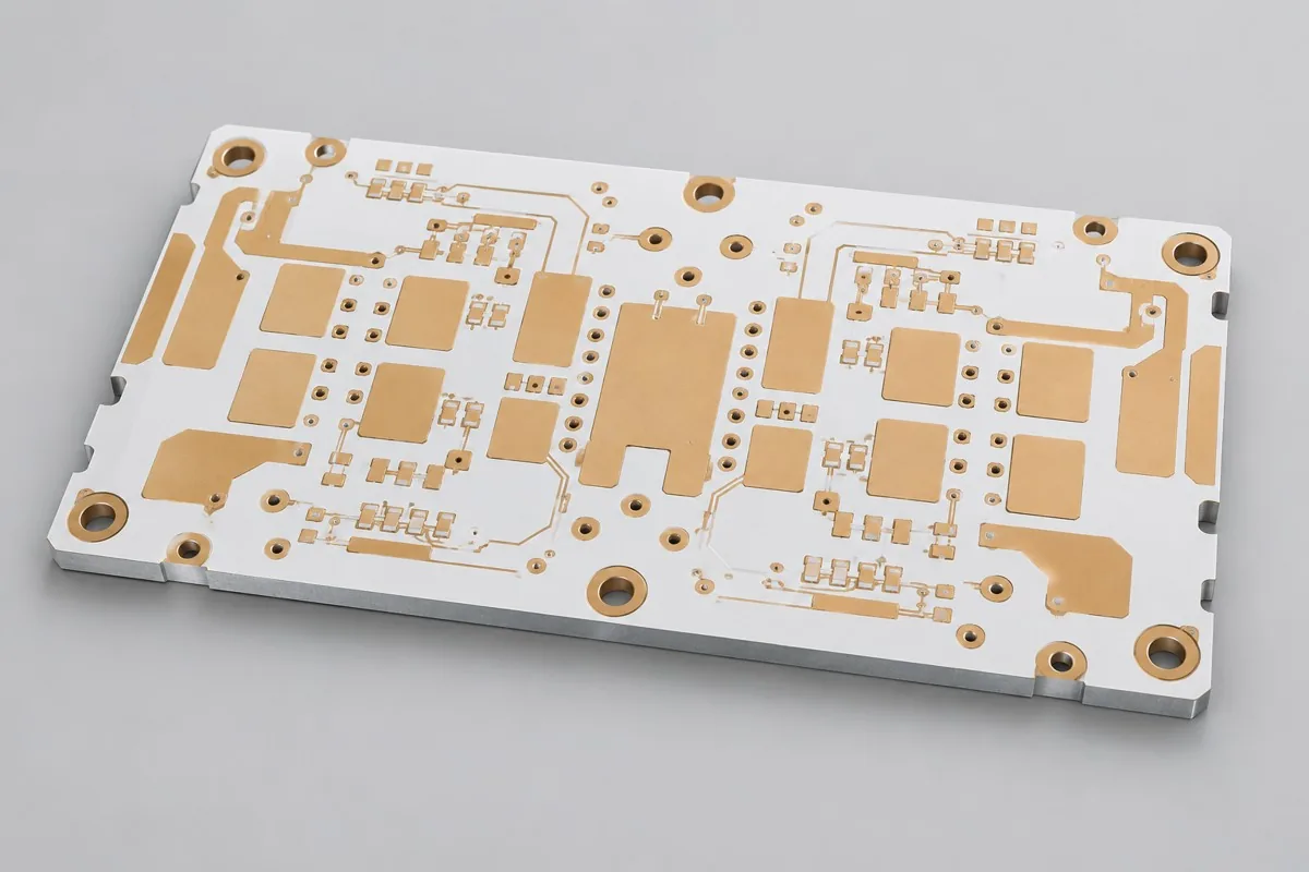
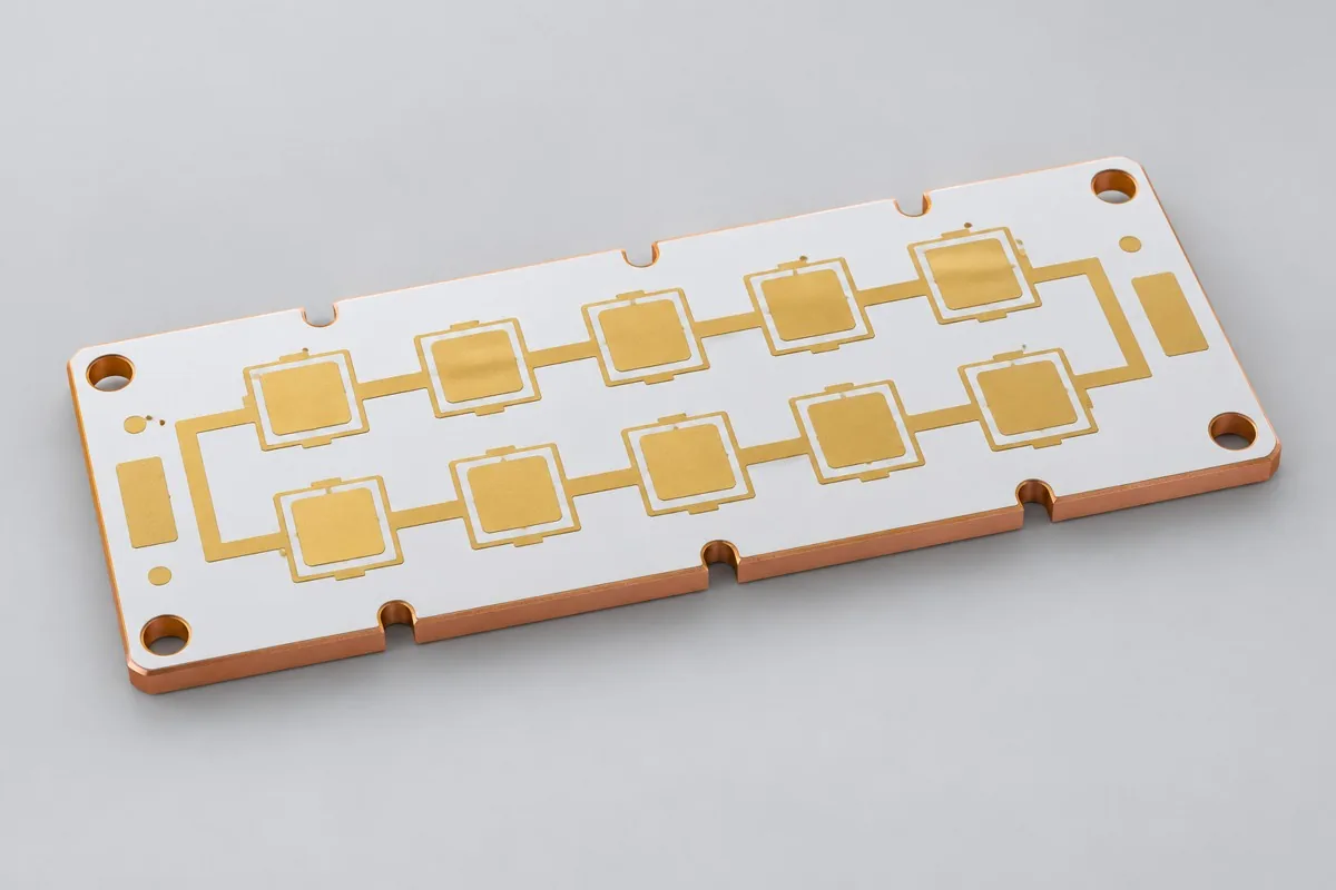
Insulated copper-core LED board fabrication requires review against current fabrication drawings. Procurement of bare boards requires C1100 copper bases, HPL-03602 dielectric, and clamped-mounting drawings. Compare copper-base weight and cost together with dielectric thermal resistance; this structure retains insulation. Deliver mounting-surface and circuit-to-copper-base insulation records; it is not a direct-thermal-path copper board.
Copper-core PCB fabrication first requires defining bare PCB prototyping or volume-fabrication scope. Please provide Gerber data, drill files, board outline, and layer stackup, material and process requirements, quantity, and fabrication acceptance requirements. Copper core spreads heat with an insulation layer; it differs from boards with dielectric-free direct thermal paths
Why choose this structure for an insulated copper-core LED board?
For concentrated high-power LED heat sources, a copper base offers another heat-spreading structure; this page's insulated C1100 copper-core board is an option. HPL-03602 nominal 50µm dielectric and manufacturer ASTM D5470 thermal conductivity of 3.0W/(m·K) are material inputs. This is an insulated copper-core product, not a direct-thermal-path board with a direct copper pedestal connection.
Why do copper-core and aluminum-core PCB quotes differ?
Copper-base materials, weight, and fabrication differ from aluminum core. This product also requires HPL-03602 insulating dielectric, 70µm circuit copper, ENIG, and underside oxidation protection. For specified thermal validation, additionally list LEDs, interface materials, and heatsink conditions. Align board shape, dielectric, and thermal boundaries for price comparisons; same-area metal unit prices cannot estimate whole-board costs.
Quotation terms depend on the approved files, quantity, material supply, tests and delivery requirements.
Prepare a structured RFQ or use the short inquiry form.
Enter the following items in one itemized quotation: specify cost units and tax/shipping basis, with separate columns for first orders and same-revision repeat orders. The table is a procurement breakdown method, not a ready-made price list; reference specifications require approval against current fabrication drawings.
| Quotation items and pricing boundaries | Configuration inputs to confirm | Repeat orders and revision changes |
|---|---|---|
| Materials/fabrication, quoted per batch or accepted board | C1100 copper base+TCLAD HPL-03602 insulating dielectric (reference procurement combination); 1 copper layer; circuit base copper 70µm/finished copper target 70µm; copper base and circuit copper defined separately | Recurs on repeat orders; material, layer-order, or copper-weight changes require requotation |
| Holes and forming, per approved hole table | NPTH Ø3.20mm mounting holes; no default electrically isolated direct-thermal-contact pedestal | Repeat orders follow same-revision fabrication; check processes before changing copper-core insulation boundaries |
| Surface finish/packaging, noting areas and batches | ENIG pads; define rear-copper oxidation protection and thermal interfaces separately | Incurred by actual batch; confirm packaging, storage conditions, and surface-finish substitutions separately |
| Engineering/tooling preparation, identifying one-time or per-batch charges | Copper-core insulation boundaries: provide LED pads and exposed copper-base regions, distinguishing insulated copper core from direct-copper-contact structures. | Verify file revisions, ownership, and storage condition before reusing old tooling; do not assume reuse is free |
| Structural/special inspections, identifying coupons, hole groups, or samples | Mark insulating-dielectric boundaries in fabrication drawings and deliver corresponding dimensional/insulation inspections. Validate copper-core cooling under specified interface conditions; copper material names alone cannot determine thermal performance or quotation scope. | List initial prototype validation and per-batch sampling separately; quote per-board requirements separately rather than assuming everything is completed once |
| Delivery scope, reports, and accepted quantity | Bare insulated copper-core PCB, circuit/base-copper material drawings, and mounting-surface/insulation records; agreed thermal-validation data and surface-finish descriptions. | Retain revision links and batch records on repeat orders; list component assembly, firmware, and complete-unit testing separately |
How do insulated copper-core and direct-thermal-path copper-core boards differ?
The current copper-core structure retains HPL insulating dielectric; LED pads do not connect directly to the copper base. Direct copper pedestals with separate thermal and electrical paths involve different structures and fabrication and cannot be inferred from the copper-core name. Compare this product with aluminum core by heat spreading, weight, and cost under identical mounting conditions; copper's thermal conductivity does not replace whole-board thermal resistance.
| Comparison Dimension | Copper-core PCB fabrication | LED strip aluminum substrate fabrication |
|---|---|---|
| Material and Grade | C1100 copper base+TCLAD HPL-03602 insulating dielectric (reference procurement combination) | 5052 aluminum base+TCLAD HT-04503 insulating dielectric (reference procurement combination) |
| Layer Count and Structure | 1 copper layer | 1 copper layer |
| Hole Structure and Dimensions | NPTH Ø3.20mm mounting holes; no default electrically isolated direct-thermal-contact pedestal | NPTH Ø3.20mm mounting holes; strip cutouts clear copper |
| Application | Spotlight LED modules; optical LED boards with concentrated heat sources | Linear LED strips; bare lighting boards with distributed heat sources |
How many watts can a high-power LED copper-core board handle?
Calculate and validate using LED heat sources, pads, power dissipation, dielectric, and heatsink. This product's 50µm HPL dielectric and 3.0W/(m·K) material value cannot directly establish rated power; mounting flatness and contact surfaces also affect results. Select by permitted component temperature rather than maximum-wattage labels alone.
| Decision Sequence | Required project inputs | Agreed records and deliverables |
|---|---|---|
| 1. Define application and scope | Provide LED pads and exposed copper-base regions, distinguishing insulated copper core from direct-copper-contact structures. | Mark insulating-dielectric boundaries in fabrication drawings and deliver corresponding dimensional/insulation inspections. |
| 2. Confirm structural requirements | Include clamping, thermal-material, and mounting-hole drawings to define underside and hole-edge acceptance. | Validate copper-core cooling under specified interface conditions; copper material names alone cannot determine thermal performance or quotation scope. |
| 3. Align nets with fabrication targets | Not a controlled-impedance product; define dielectric withstand separately from dielectric/system insulation design | Provide target nets, layer pairs, and validation scope; review together with NPTH Ø3.20mm mounting holes and no default electrically isolated direct-thermal-contact pedestal |
| 4. Confirm quotation and release revision | C1100 copper base+TCLAD HPL-03602 insulating dielectric (reference procurement combination); 2.00mm reference target; ENIG pads; define rear-copper oxidation protection and thermal interfaces separately | Request quotations using material/pattern/inspection lists at the same revision; list unapproved substitutions as separate alternatives rather than including them in the baseline quotation |
Insulated copper-core LED board manufacturing specifications
| Specification Items | Reference configuration or target |
|---|---|
| Material and Grade | C1100 copper base+TCLAD HPL-03602 insulating dielectric (reference procurement combination) |
| Layer Count and Structure | 1 copper layer |
| Total Board Thickness | 2.00mm reference target |
| Dielectric thickness and interlayer relationship | HPL-03602 nominal dielectric 50µm; the reference finished board retains this insulation layer |
| Base Copper and Finished Copper | Circuit base copper 70µm/finished copper target 70µm; copper base and circuit copper defined separately |
| Hole Structure and Dimensions | NPTH Ø3.20mm mounting holes; no default electrically isolated direct-thermal-contact pedestal |
| Trace Width and Spacing | 0.30/0.30mm reference design |
| Impedance Target and Measurement Methods | Not a controlled-impedance product; define dielectric withstand separately from dielectric/system insulation design |
| Surface Finish | ENIG pads; define rear-copper oxidation protection and thermal interfaces separately |
| Original Material Specifications | HPL-03602: nominal dielectric 50µm; HPL thermal conductivity 3.0W/(m·K), manufacturer ASTM D5470 value, not whole-board thermal resistance |
| Application | Spotlight LED modules; optical LED boards with concentrated heat sources |
| Deliverables | Bare insulated copper-core PCB, circuit/base-copper material drawings, and mounting-surface/insulation records; agreed thermal-validation data and surface-finish descriptions. |
Insulated copper-core LED board layer order and hole structure
The following shows functional layer order/material structure for this reference configuration, not a production stackup drawing; do not infer thickness from graphic proportions. Match copper-layer numbering to via layer pairs item by item in approved fabrication files.
| Top to Bottom | Layer Responsibilities/Structure |
|---|---|
| Structure 1 | LED Circuit Copper |
| Structure 2 | Insulating dielectric HPL-03602 |
| Structure 3 | C1100 copper base (not a circuit layer) |
Hole structure: NPTH Ø3.20mm mounting holes; no default electrically isolated direct-thermal-contact pedestal
HPL-03602 insulation and thermal-conductivity data
HPL-03602 nominal 50µm dielectric and 3.0W/(m·K) are manufacturer material data; thermal conductivity uses ASTM D5470. Confirm finished-board dielectric thickness, insulation tests, and installed thermal interfaces separately. Include heatsink contact surfaces and material revisions with RFQs so thermal testing matches actual assembly conditions.
Trade-offs between copper-base weight and insulation-layer thermal resistance
Copper bases are generally heavier than aluminum and have higher material/fabrication costs; compare whole-board benefits under actual thermal boundaries. Insulation remains part of the thermal path. Copper core does not mean LED pads connect directly to the base, and target thermal conductivity cannot establish maximum power.
Underside oxidation protection, mounting holes, and edge burrs: fabrication inspection
Define base copper separately from circuit copper, and control mounting-hole/edge burrs to prevent bridging. Oxidation protection on thermal surfaces must preserve subsequent contact; match LED pad flatness to component-soldering requirements. Pedestal machining or dielectric removal is not included by default.
Circuit-to-copper-base insulation and thermal interfaces: acceptance items
Measure dielectric thickness, copper weight/flatness, and circuit-to-base insulation. Perform thermal tests with specified LEDs, power dissipation, thermal materials, and heatsinks, comparing temperature rise with aluminum-core alternatives under identical mounting conditions.
Insulated copper-core LED board delivery scope
Applications: spotlight LED modules; optical LED boards with concentrated heat sources.
Bare insulated copper-core PCB, circuit/base-copper material drawings, and mounting-surface/insulation records; agreed thermal-validation data and surface-finish descriptions.
Exposed copper-base regions and clamped-mounting surfaces: RFQ inputs
Submit exposed copper-base regions and clamped-mounting surfaces to turn tabled design targets into inspectable fabrication drawings. The following inputs define pattern, material, or structural inspection scope; freeze the quotation revision with approved drawings.
| Project inputs required for review | Engineering decisions | Records/delivery as agreed in the order |
|---|---|---|
| Copper-core insulation boundaries | Provide LED pads and exposed copper-base regions, distinguishing insulated copper core from direct-copper-contact structures. | Mark insulating-dielectric boundaries in fabrication drawings and deliver corresponding dimensional/insulation inspections. |
| Thermal Mounting Surface | Include clamping, thermal-material, and mounting-hole drawings to define underside and hole-edge acceptance. | Validate copper-core cooling under specified interface conditions; copper material names alone cannot determine thermal performance or quotation scope. |
Copper-core PCB fabrication: pricing, selection, and procurement FAQ
Why do copper-core and aluminum-core PCB quotes differ?
The complete budget is materials/base fabrication + excluded profiling + specified inspection + taxes and shipping, divided by the delivered board quantity. A project-specific quotation requires review of the available files, quantity, materials, requested tests, delivery destination, taxes, shipping, and trade terms. These hypothetical amounts do not represent current market pricing for this product. No current unit prices are published here; request an itemized quotation for the approved scope.Review quotation inputs and scope.
How do insulated copper-core and direct-thermal-path copper-core boards differ?
This product retains HPL insulation between circuits and the copper base; LED pads do not connect directly to base copper. A direct-thermal-path pedestal is another structure requiring separate cross sections and processes. The copper-core name does not establish absence of dielectric thermal resistance. Review the comparison
How many watts can a high-power LED copper-core board handle?
Neither copper core nor material thermal conductivity establishes a universal wattage. LED power dissipation, pads, dielectric, interface materials, and heatsinks jointly determine component temperature; calculate and measure against permitted temperatures. This product's 50µm dielectric does not establish whole-board rated power. Review the comparison
Will a copper-core board always run cooler than an aluminum-core LED board?
Compare under identical heat-source, dielectric, and mounting boundaries; insulation and contact may dominate thermal resistance. Copper is heavier and costs differ, so testing is needed to determine whether replacing any LED board with copper is worthwhile.
Does a copper-core board quotation include a pedestal with the insulation removed?
This product does not include pedestals or dielectric-removal structures by default. For direct thermal pedestals, provide cross sections for separate process and insulation review; the current insulated HPL board quotation does not apply directly.
Can underside oxidation protection be chosen freely for copper-core boards?
Underside treatment must match thermal interfaces and assembly contact; appearance-focused oxidation protection must not impair thermal contact. Specify underside purpose, flatness, and surface condition in procurement, and validate with final installation.
How can incorrect quotations be avoided between insulated copper-core and direct-copper-contact boards?
Provide cross sections showing LED pads, exposed copper regions, and insulating-dielectric boundaries, specifying whether thermal pads connect directly to the copper base. The structures have different fabrication and insulation responsibilities. Approve thermal/electrical boundaries before RFQ; copper material names or thermal conductivity cannot replace mounting-interface thermal validation.
How can per-board and per-panel quotations for copper-core PCB fabrication be converted?
Define circuit copper and copper-base cutting separately. Mounting holes, rear-copper oxidation protection, and thermal contact cannot be quoted using only conventional aluminum-core panel processes. Specify deliverable finished-board quantity per panel, actual panel purchasing quantity, and individual-board/panel delivery state. Calculate fabrication cost per board by dividing actual panel fabrication cost by the corresponding accepted finished-board quantity; list preparation, special inspection, and packaging separately. Theoretical utilization cannot promise yield.
How should first-order one-time costs and repeat-order costs be separated for copper-core PCB fabrication?
For the first order, confirm documentation for copper-core insulation boundaries and thermally conductive mounting surfaces, identifying whether related engineering, tooling, or test preparation is charged once. Mark insulating-dielectric boundaries in fabrication drawings and deliver corresponding dimensional/insulation inspections. Before reusing tooling, verify files and ownership. This batch still incurs materials, fabrication, and approved inspections; separately list preparation that must be repeated after changes rather than relying on the old order total.
Can I get a copper-core PCB fabrication budget before insulation-boundary information is complete?
Start with the application, board outline, quantity, and available drawings to obtain a budget identifying missing inputs. Formal review requires LED pads and exposed copper-base regions, distinguishing insulated copper core from direct-copper-contact structures. Corresponding deliverables require insulating-dielectric boundaries marked in fabrication drawings and corresponding dimensional/insulation inspections. Confirm fabrication/inspection quotations after these conditions are frozen. Initial inquiries need not include every file, but estimates do not imply coverage of undefined structures.
What must be reconfirmed when changing materials, hole tables, or mounting conditions on repeat orders for copper-core PCB fabrication?
Include clamping, thermal-material, and mounting-hole drawings to define underside and hole-edge acceptance. Validate copper-core cooling under specified interface conditions; copper material names alone cannot determine thermal performance or quotation scope. Match each changed location against prior material/hole-table/mechanical files to determine whether drawings, processes, or measurements need updating. Retaining only the product name and layer count cannot establish identical repeat-order conditions.
When two copper-core PCB fabrication quotations specify the same material, which configurations still need checking?
Compare C1100 copper bases and HPL insulation, explicitly identifying any direct-copper-contact pedestal. This product retains dielectric and does not include a direct-thermal-path pedestal by default; thermal validation requires actual clamping and interfaces.
Which reports should link to board IDs before copper-core PCB fabrication moves from prototypes to volume production?
Mark insulating-dielectric boundaries in fabrication drawings and deliver corresponding dimensional/insulation inspections. Validate copper-core cooling under specified interface conditions; copper material names alone cannot determine thermal performance or quotation scope. Link material batches, approved fabrication files, and these inspection results to current prototype IDs; use the revision with issues closed for volume production. Reports for old coupons or patterns support comparison but cannot replace current fabrication inputs. Define separate scope for complete-unit items not yet covered.
If small-batch copper-core PCB unit prices fall, how can I determine whether total procurement costs really decrease?
Confirm thermal/electrical boundaries first for insulated copper-core and direct-copper-contact approaches; quote added pedestals and interface validation separately. The current insulated HPL board price does not represent a finished direct-thermal-path module. Total preparation, fabrication, agreed inspection, packaging, and shipping, then divide by accepted delivery quantity to compare total and per-board costs at equal scope. Use current RFQ amounts and rates rather than assuming a fixed reduction.
Comparing insulated copper-core LED boards with related board types
Current configuration distinction: copper core spreads heat with an insulation layer; it differs from boards with dielectric-free direct thermal paths
- Double-sided insulated IMS driver module board — Circuits on both sides and holes insulated from the metal core form a separate product, more complex than single-sided IMS
Metal substrate complete product catalog · All PCB Products
Material and design basis for insulated copper-core LED boards
- Engineering reference | Thermal via design rules: hole-wall copper, filling, and interface contact: structural reference; supplier capacity claims do not transfer
- Engineering reference | PCB thermal estimates: power dissipation, copper area, and junction-temperature checks: Thermal design methods
- Engineering reference | Thermal Clad metal-core PCBs: dielectric thermal-conductivity and insulation selection: material dielectric thickness/ASTM D5470 thermal-conductivity values; the reference stackup is not a manufacturer standard for complete boards
When citing the above materials, record material revisions and design conditions for C1100 copper bases and HPL-03602 dielectric; first-article review focuses on circuit-to-base insulation and thermal interfaces. If materials, copper weight, or via structure change, update fabrication drawings and inspection items before release.
Request Quote for This PCB Configuration: reference product ID 244, include critical circuits/interfaces and quantity, and identify specifications to retain or adjust.