Engineering Reference Configuration
Instrument PCB assembly: configurations and test deliverables
The following adjustable engineering configurations support material, functional, and process review; they are not stocked models or commitments to current production-line capabilities. Approved fabrication documentation and order acceptance requirements govern.
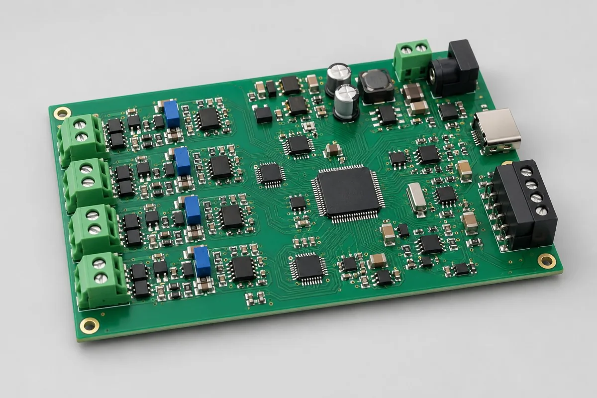
Low-volume instrument acquisition assembly supports contract manufacturing and procurement review for 4-channel voltage/current inputs. Confirm MCU + ADC + precision reference/filtering, RS-485 or USB, terminal inputs, debug ports, and 4-layer FR-4 with analog/communication partitioning. Compare SMT → secondary interface soldering → programming → range-specific calibration and zero/span, multichannel, communication, and power-loss retention acceptance costs. This page separates prototype/low-volume boards + calibration tables + change/test records from separately designed voltage/4–20mA reference front ends to clarify actual quote coverage. RFQ file reference:BOM · bare board · material supply
Reference specification and configuration options
| Options | Reference Configuration |
|---|---|
| Power and Logic Domains | 24V or 5V power supply options |
| Functional Module | Four-channel voltage/current instrument inputs |
| Core Components/Architecture | MCU + ADC + precision reference/filtering |
| Interface and Channels | RS-485 or USB; terminal inputs; debug port |
| Board Layers and Material Options | 4-layer FR-4 baseline; analog/communication partitioning |
| Component types | QFN ADCs, precision parts, terminals, and replaceable front ends |
| Assembly Route | SMT → secondary interface soldering → programming → range-specific calibration |
| Material Supply Scope | Specified critical precision parts; prototype front ends may be procured by revision |
| Firmware and Parameters | Measurement ranges, units, filtering, calibration, and communication parameters |
| Test Focus | Zero/span, multichannel, communication, and power-loss retention |
| Deliverables | Prototype/low-volume boards + calibration tables + change/test records |
| Configuration Limits/Options | Separately designed voltage/4–20mA reference front ends |
How much does low-volume instrument acquisition assembly cost, and what is included?
Precision ADCs, references, front-end resistors, and terminals affect material costs. Range-specific component changes, zero/span calibration, and calibration readback are major low-volume tasks. Prepare and record front-end revisions separately. Four-channel counts alone overlook voltage versus 4–20mA circuit differences.
Quotation terms depend on the approved files, quantity, material supply, tests and delivery requirements.
Prepare a structured RFQ or use the short inquiry form.
| Cost Item | Scope for This Configuration | Billing frequency and work scope | Procurement Verification |
|---|---|---|---|
| Bare PCB and core components | MCU + ADC + precision reference/filtering; 4-layer FR-4 baseline; analog/communication partitioning | Price according to actual bare-board/component purchase quantities; authorize critical components and substitutions individually | Specified critical precision parts; prototype front ends may be procured by revision |
| Placement and Post-Assembly | SMT → secondary interface soldering → programming → range-specific calibration | Feeder/program setup per lot; assembly priced per board, joint, or process as agreed, with counting rules specified | QFN ADCs, precision parts, terminals, and replaceable front ends |
| Manufacturing Preparation | Review stencils, first articles, and support tooling against the actual assembly route | New stencils/carriers may be separate one-time charges; verify panelization, revision, and condition before reuse | Reduced quantities do not automatically eliminate first-article or feeder setup |
| Functional Support | Zero/span, multichannel, communication, and power-loss retention | Itemize test-method/fixture/script setup; agree execution charges per board, channel, or test duration | Separate supporting development from execution records for each board |
| Software and Parameters | Measurement ranges, units, filtering, calibration, and communication parameters | When firmware exists, distinguish file programming/verification from software development; omit programming without a firmware revision | Customer-approved files, parameters, and readback rules determine scope |
| Delivery and Change | Prototype/low-volume boards + calibration tables + change/test records; separately designed voltage/4–20mA reference front ends | Price accessories, retesting, and revision changes by approved work items; do not prefill fixed rates | Check BOM, tooling, programs, and acceptance revisions before reorders |
How do voltage and 4–20mA instrument input boards differ?
Front ends, protection, conversion relationships, and calibration sources differ. Even with identical ADCs, changing displayed units does not make them interchangeable. Select revisions from sensor outputs and wiring first.
| Comparison Metric | Current Conditions | Factors Influencing Procurement Decision |
|---|---|---|
| Manufacturing Delivery | SMT → secondary interface soldering → programming → range-specific calibration | Produce boards/assemblies per BOM and assembly drawings; this does not establish that every system function passes |
| Functional Acceptance | Zero/span, multichannel, communication, and power-loss retention | Compare unit prices after defining test stimuli, limits, accessories, and records; review missing test inputs first |
| Configuration Options | RS-485 or USB; terminal inputs; debug port; 4-layer FR-4 baseline; analog/communication partitioning | Confirm circuit/program compatibility before reviewing assembly and test costs for interface, stackup, or component changes |
| Delivery Scope | Separately designed voltage/4–20mA reference front ends | Complete-system accessories, application development, and project verification are not automatically included in board assembly |
Is a high-resolution ADC enough for an instrument acquisition board?
Reference drift, protection leakage, filtering, and wire resistance also affect readings. Specify measurement ranges, units, bandwidth, and calibration conditions, then compare measured channels. Bit count alone is not board accuracy.
- First list required 4-channel voltage/current instrument inputs, distinguishing build-to-print work, configuration changes, and new function development.
- Then freeze full MCU + ADC + precision reference/filtering part numbers, RS-485 or USB, terminal inputs, debug ports, and 4-layer FR-4 with analog/communication partitioning. Split customer supply and procurement using specified precision parts and separately procured prototype front-end revisions.
- Use first articles to verify SMT → secondary interface soldering → programming → range-specific calibration, plus ranges, units, filtering, calibration, and communication parameters. For supplied files, agree writing verification first; review development separately.
- Turn zero/span, multichannel, communication, and power-loss retention into acceptance tests with stimuli, limits, and records. Define fixture ownership, per-board execution, and post-rework retesting.
- Finally confirm prototype/low-volume boards + calibration tables + change/test records and separately designed voltage/4–20mA reference front ends. Compare totals at equal quantities, accessories, and test scope, then freeze the order revision.
Applicable uses and situations requiring separate review
Sensor measurement-range verification and instrument acquisition prototypes.
For high-speed synchronization or large buffers, compare FPGA/8-channel A/D options. Display digits do not establish measurement accuracy. No accuracy commitment is made without references and error budgets.
Assembly Challenges for This Product
Review precision reference, input filter, and protection assembly/cleaning together. Mark ranges on board IDs for low-volume variants; calibration fixtures must not guess revisions through software. Perform final zero/span calibration after terminal soldering.
Structural, thermal, and configuration trade-offs
Jumpers or replaceable resistors ease range exploration, but every component change requires recalibration. Higher ADC resolution does not eliminate reference drift, protection leakage, or test-lead resistance.
Product-specific test matrix
| Test stage | Inspection/Functional Methods | Acceptance Record |
|---|---|---|
| Range Calibration | Inject zero/mid/end point per channel | Raw value, coefficient, and reference source |
| Channel/Interface | Single channel excitation and communication readback | Channel mapping, crosstalk, and unit |
| Parameter Save | Modify measurement range, power off then read | Coefficient, parameter, and program version |
Defect Handling and Acceptance
Writing coefficients to wrong boards, wrong input-network values, and wiring confusion are prototype risks. Establish variant-specific limits and range labels. Recalibrate after analog-path rework and record component-change reasons.
Low-volume instrument PCB assembly: material supply and revision management
Lock critical resistor, reference, and ADC part numbers. Customer-supplied precision parts include packaging and lots. Proposed substitutes must state error/drift conditions; identical resistance alone is insufficient for approval.
Prototyping vs. Production Differences
Use initial batches to establish error budgets and calibration methods. Before production, freeze ranges, test points, and fixtures, removing uncontrolled debug jumpers so calibration results trace to board IDs.
Delivery Configuration
Prototype/low-volume boards + calibration tables + change/test records. Separately designed voltage/4–20mA reference front ends.
Convert this configuration into a reviewable order
At ordering, check BOM, quantity, material supply, and conditions below. Supply pick-and-place files, DNP, and assembly drawings for SMT. For programming, provide range, unit, filtering, calibration, and communication files with writing rules and verification. For calibration within zero/span, multichannel, communication, and retention tasks, add ranges/references, limits, and parameter-writing requirements. Review materials, SMT → secondary soldering → programming → range calibration, stencil/loading, support carriers, and test setup costs separately. Reapprove file revisions and agree milestones after material readiness and scheduling.
| Required project inputs | Engineering Decisions Affected | Records/delivery as agreed in the order |
|---|---|---|
| Instrument Input Mode | Mark voltage/current input, range, and wiring per channel to determine sources and divider/sensing resistance. | Record each channel's zero/full-scale results and parameter checksums; one channel's calibration cannot replace the others. |
| Prototype Adjustable Items | List replaceable resistors, jumpers, and formal production configurations. | Link debug changes to BOMs and firmware so test reports do not retain old ranges. |
Low-volume instrument acquisition assembly FAQ
How much does low-volume instrument acquisition assembly cost, and what is included?
For standard placement, first calculate board quantity × billable points per board × price per point + setup fee. A project-specific quotation requires review of the available files, quantity, materials, requested tests, delivery destination, taxes, shipping, and trade terms. This is a placement-only reference; bare PCBs, materials, and testing are charged separately. Any formula on this page organizes cost inputs; it is not a quoted rate.View cost items, calculation conditions, and sources.
How do voltage and 4–20mA instrument input boards differ?
Front ends, protection, conversion relationships, and calibration sources differ. Even with identical ADCs, changing displayed units does not make them interchangeable. Select revisions from sensor outputs and wiring first.
Is a high-resolution ADC enough for an instrument acquisition board?
Reference drift, protection leakage, filtering, and wire resistance also affect readings. Specify measurement ranges, units, bandwidth, and calibration conditions, then compare measured channels. Bit count alone is not board accuracy.
Does changing one range on a low-volume instrument board incur new fees?
Front-end or parameter changes need affected-channel recalibration and possibly changed sources/fixtures. Quotes should list component changes, calibration, and revision work between original and new ranges, rather than treating this as relabeling.
What should an instrument board outgoing calibration table include?
Include range revisions, reference points, raw or converted results, and coefficient/firmware relationships. Records follow boards to prevent calibration parameters from other ranges being written to identical hardware.
Can four-channel instrument boards share coefficients across different units?
Ranges, unit conversions, and front ends have specific conditions. Coefficients must match channels and revisions. Recalibrate changed front ends and read back parameters before shipment to avoid plausible readings with wrong units or spans.
How should replaceable front-end comparisons be organized for low-volume instrument boards?
Identify each front end as a separate BOM variant, retaining zero/span, filtering, and source results separately. Separate setup from component-change/calibration costs to identify circuits suitable for production.
How should range calibration tests enter low-volume instrument acquisition purchasing acceptance?
The reference method injects zero/midpoint/endpoint inputs into each channel, recording raw values, coefficients, and references. Provide inputs, configurations, and limits, then agree first article and per-board scope. Price setup separately from each execution. Without limits, review methods first; completed operations do not establish compliance.
How should channel/interface tests enter low-volume instrument acquisition purchasing acceptance?
The reference method stimulates one channel and reads back communication data, recording mapping, crosstalk, and units. Provide inputs, configurations, and limits, then agree first article and per-board scope. Price setup separately from each execution. Without limits, review methods first; completed operations do not establish compliance.
How should parameter-retention tests enter low-volume instrument acquisition purchasing acceptance?
The reference method changes ranges, cycles power, and rereads data, recording coefficients, parameters, and firmware revisions. Provide inputs, configurations, and limits, then agree first article and per-board scope. Price setup separately from each execution. Without limits, review methods first; completed operations do not establish compliance.
How are writing and development priced separately when customers supply instrument acquisition firmware?
Controlled content includes ranges, units, filtering, calibration, and communication parameters. Writing approved files, loading parameters, and readback verification are manufacturing execution; new logic, interface adaptation, or algorithm changes require development review. Quote setup, per-board writing, verification, and failure handling separately. Programming included does not imply application development.
Do repeat low-volume instrument acquisition orders need recalculated first article, stencil, and loading fees?
The route is SMT → secondary interface soldering → programming → range-specific calibration. Check stencils/panels for SMT and supports/assembly for through-hole or later installation. Agree batch loading and first articles; reuse tooling only when revision, location, and condition match. After QFN ADC, precision part, terminal, or replaceable front-end changes, assess tooling and zero/span, multichannel, communication, and retention impacts before confirming recurring fees.
How should total instrument acquisition costs be compared with customer-supplied critical parts and procured remaining materials?
Create a responsibility table using specified precision parts and separately procured prototype front-end revisions. Confirm full part numbers, quantities, packaging, and excess material rules. Customer supply changes only procurement boundaries. SMT → secondary soldering → programming → range calibration and zero/span, multichannel, communication, and retention remain actual work. Approve shortage, substitution, or lot-change impacts first. Do not compare customer-supplied component prices directly with material-inclusive assembly totals.
What needs retesting after low-volume instrument acquisition rework or supplemental orders?
Select retests by change impacts. Original acceptance covers zero/span, multichannel, communication, and retention, with prototype/low-volume boards + calibration tables + change/test records. If rework affects power, interfaces, critical analog circuitry, or software, check related tests rather than only repaired joints. Align supplemental orders with original BOMs, parameters, and setups. Agree fees by approved items and actual quantities, without assuming free retests or fixed turnaround.
Compare Other Products in This Category
- Small-Batch Wireless Speaker Control Board: Wireless audio and acoustic tuning.
When initial design files must be created
Four-channel isolated 4–20mA process acquisition board design: Provides access to corresponding circuits/layouts and verification plans. Channels, interfaces, or mechanics may differ from this page's engineering reference and require independent design revisions. Design-stage deliverables include source files, BOMs, layout constraints, and verification records. Assembly procurement on this page delivers actual PCB assemblies/components, programmed revisions, and product-test records against approved files.
Return to low-volume PCB assembly configuration comparison · Component Supply and Procurement · Testing and Delivery Scope
Material and Process Reference
- Engineering reference | SMT packages and assembly methods: pads, stencils, and thermal processes: a package/assembly method index only; not evidence that the product configurations on this page are models produced by KFPCBA
- Engineering reference | Soldering processes and defect isolation: wetting, residues, and solder oxidation: a reference entry for soldering, residues, and defect isolation methods only. Verify this page's soldering routes against specific materials/components