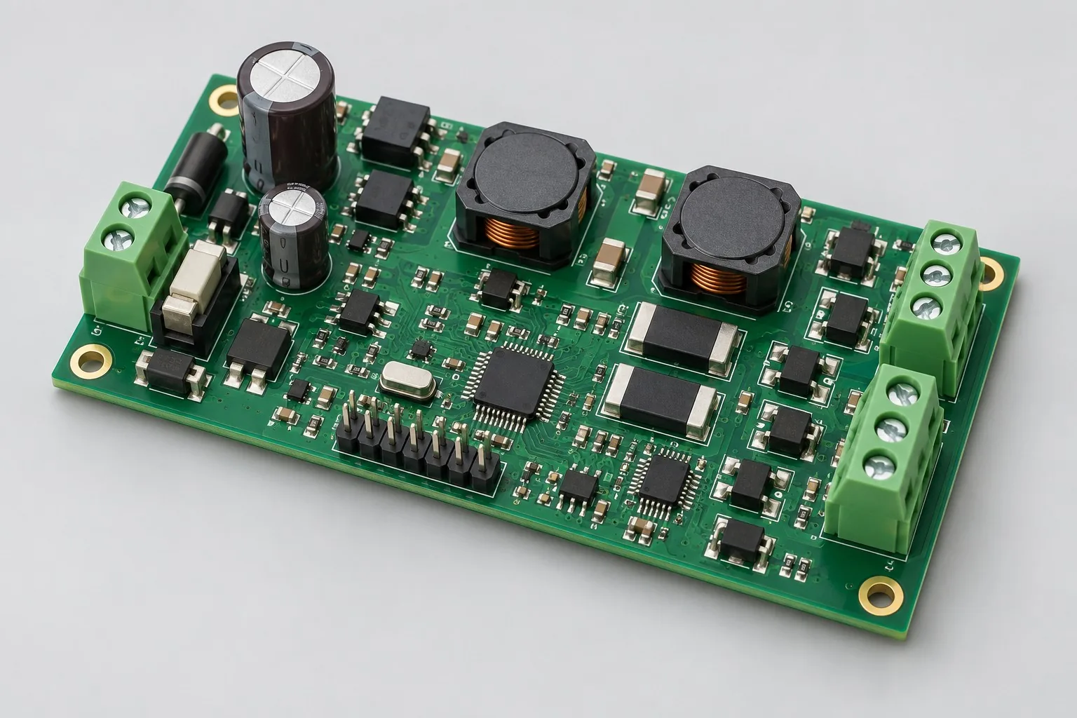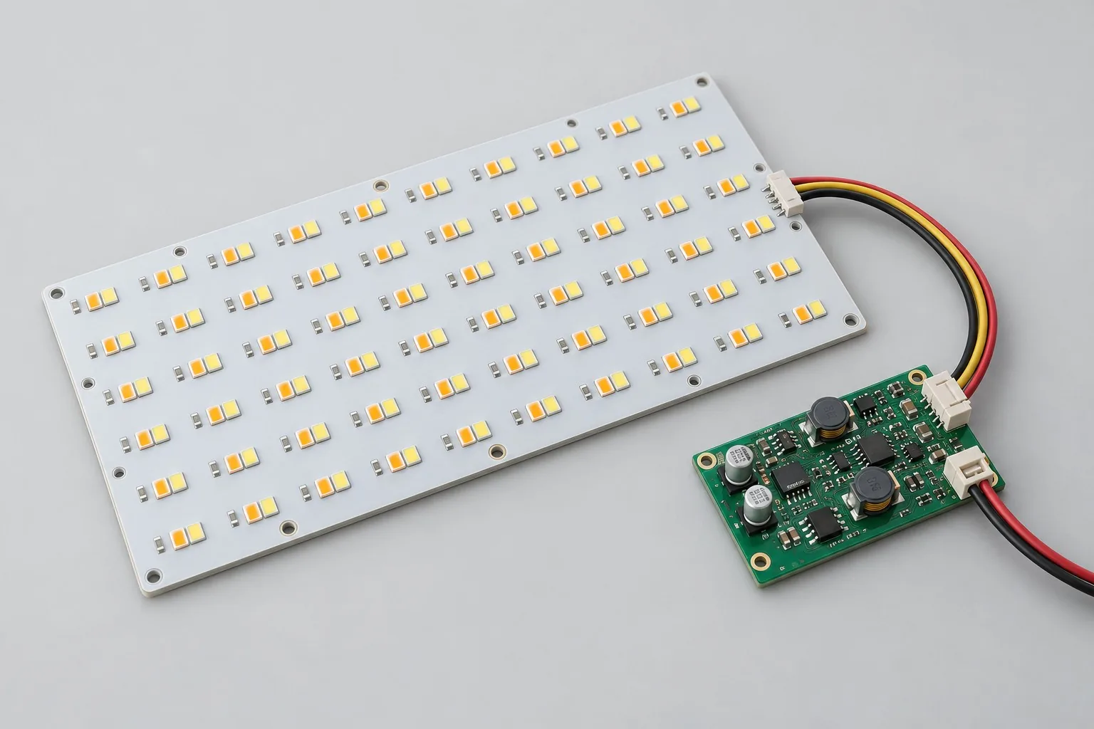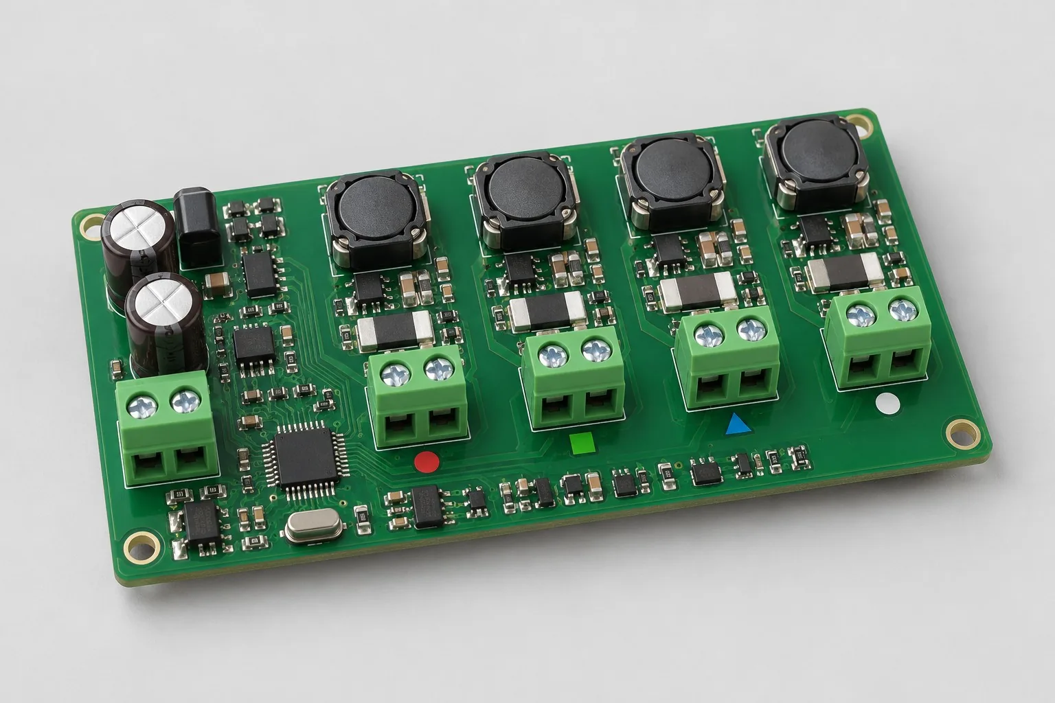
Engineering reference design · prototype validation pending
RGBW control board design: four-channel RGBW constant-current color mixing
The RGBW constant-current color-mixing control board independently drives red, green, blue, and white LED groups, using dimming and measured lookup tables to create scene colors. The 350mA-per-channel target is an example. Calculate each channel’s forward voltage, simultaneous supply loading, and thermal derating separately; use a different architecture for constant-voltage strips.
Custom development reference design. The parameters below are requirement configurations and design targets; validate product performance through agreed prototype tests.
| Functional Partition | Design and Inspection Objects |
|---|---|
| RGBW channel requirements | Freeze RGBW LED bins, series counts, Vf, and optical targets separately; define the white channel’s role and color-mixing approach first. |
| Four-Channel Constant Current Driver | Compare four buck constant-current channels with a multichannel driver; design each channel independently for voltage difference and inductor/switch stress. |
| Color Mixing / Dimming Control | The MCU provides dimming, scenes, and configuration retention after power loss; define commands/addresses separately for optional RS485. |
| LED and optical output | Prevent misconnection at each output; the actual LED board and diffuser structure jointly determine color mapping. |
| DC power supply and thermal management | Review the 24V input with all four channels at full load simultaneously; measure driver/LED-board hot spots for derating. |
| Channel Calibration / Protection | Measure current and ripple for individual and simultaneous four-channel operation. After color/PWM calibration, verify the remaining channels’ states during faults and scene transitions. |
How much does RGBW design cost, and how is it quoted?
RGBW development fees must cover four-channel current control and color mixing. Constant-current LEDs and constant-voltage strips use different hardware. Minimum brightness, scene transitions, optical calibration, and concurrent cooling requirements affect effort. Itemize driver circuitry, scene firmware, calibration with actual LEDs, and prototypes instead of estimating by output-channel count alone.
Quotation terms depend on the approved files, quantity, material supply, tests and delivery requirements.
Prepare a structured RFQ or use the short inquiry form.
| Quotation Items | What services are included | What to Check When Comparing Quotes |
|---|---|---|
| Circuit and PCB Design | RGBW Four-Channel Constant Current and Color Mixing Mapping | Reusable portions of existing designs and circuit/mechanical changes |
| Software and Validation | Low-brightness, scene transitions, concurrent thermal tests | Itemize current drive, color lookup, scene protocols, optical calibration |
| Prototype Preparation | Bare PCB, BOM procurement, assembly, and agreed prototype quantity | Whether material/component revisions, prototype quantities, and test targets match |
| Subsequent Revision | Record new requirements separately from post-test corrections | How agreed changes, source files, and validation results are delivered |
How should RGBW constant-current boards and 12V RGB strip controllers be selected?
Independent constant-current LED channels and constant-voltage PWM for resistor-limited strips are different output architectures. Check LED wiring and power first, then compare channels and dimming approaches; the architectures are not directly interchangeable.
How should supplies support all RGBW channels together?
Budget each color’s forward voltage, current, and simultaneous operating state; do not extrapolate from one channel and a brightness multiplier. Verify full load, color mixing, and thermal derating separately, defining supply capacity and driver cooling together.
Does the RGBW development fee include color calibration and scene firmware?
List current drivers, color-mixing lookup tables, scene protocols, and optical calibration separately. For calibration with the actual LED assembly, specify LED lots, optical structure, and preset records. Delivering four PWM outputs alone does not complete color mixing.
Reference: four-channel RGBW constant-current mixing
| Configuration Field | Reference Configurations/Selections | Basis and Status |
|---|---|---|
| Finished Product Function | Four RGBW LED groups independently dimmed/mixed | Design Objective |
| Power Supply Objective | 24V DC requirement example | Design Objective |
| Channel Configuration | 4 constant-current channels, 350mA example target each | Design Objective |
| Output Load | Independent series counts/voltage drops by color | Design Objective |
| Driver Architecture | Compare four buck constant-current channels with multichannel drivers | Design Objective |
| Control Interface | MCU PWM; optional RS485 | Design Objective |
| User Function | Preset scenes, brightness, color, power-loss recovery | Design Objective |
| Stackup Candidate | 4-layer FR-4, separate driver/control regions | Design Objective |
| Thermal monitoring | Board temperature/light board temperature input and derating | Design Objective |
| Harness Structure | Independent output per channel, error-proofing terminals | Design Objective |
| Calibration Configuration | Color Lookup Table Based on LED / Optical Measurement | Design Objective |
| Verify Output | Current, mixing, flicker, EMI tests | Design Objective |
LED forward-voltage differences and concurrent dimming
Different LED colors have different voltage drops; calculate driver operating headroom and cooling separately.
Independent constant-current control simplifies regulation, but the four switching channels can interfere. Interleaving/synchronization strategies require component support and testing.
Map color values to PWM duty cycles through actual optical calibration; basic software does not promise accurate color.
Design budget and trade-off examples
Check design targets with engineering calculations
As a separate calculation example, four 0.3A channels at LED voltages of 9, 12, 12, and 12V deliver 0.3×(9+12+12+12)=13.5W. The 0.3A assumption differs from the 350mA-per-channel reference target; recalculate using the approved channel currents.
Conditions and Scope of Application:Freeze peak and simultaneous-conduction conditions; current or PWM ratios do not directly establish color. Agree on optical calibration and temperature-rise testing.
Replace examples with selected components and record margins; calculations support design choices, while prototype records support acceptance.
Power and layout for four-channel RGBW constant-current color mixing
- Group the four power loops compactly; route control signals from the low-noise area.
- Keep output harnesses away from the MCU and clock; keep shunt and feedback connections short.
- Budget the main power input for all four channels at full load simultaneously; distribute thermal copper evenly.
RGBW control board R&D input
- RGBW LED models, series/parallel wiring, color targets
- Control protocol, dimming frequency, and low-brightness requirements
- Relative locations of the LED board and driver, wiring harness, and cooling
If circuit files exist, provide editable schematics, PCB, BOM, and current issues, and agree on review or revision scope. If only functions are defined, freeze this page's inputs before selection and circuit development. Agree separately on control-software and external-application responsibilities, interfaces, and acceptance.
RGBW control board milestone delivery
| phase | Engineering Work for This Proposal | Reviewable Deliverables |
|---|---|---|
| Requirements and Design Freeze | Freeze the four LED groups, color and low-brightness targets, protocol, and LED board/driver locations | Functional/interface requirements, mechanical revision, acceptance conditions, and open items |
| Schematic and Component Selection | Design four constant-current channels, MCU dimming, temperature monitoring, and optional RS485 | Editable schematics, controlled BOM, footprint checks, and design calculations for these circuits |
| Layout and Routing | Lay out four compact power loops, current-sense feedback, a low-noise control area, and keyed harness connections | PCB source files, actual stackup/hole/net constraints, DRC, and assembly-dimension checks |
| Simulation/Calculation | Evaluate Vf headroom, concurrent input power, switching interference, and thermal performance separately | Design calculations/models, input conditions, margins, and items awaiting measurement |
| Prototype and Software | Build a color-mixing prototype and integrate scene lookup tables, low-brightness operation, parameter storage, and derating | Manufacturing package, RGBW prototype, agreed scene/dimming firmware, four-channel mapping, optical calibration table, and configuration recovery instructions |
| Testing and Version Closure | Test individual and simultaneous four-channel current and color mixing; check transitions from minimum to full brightness, single-channel faults, and preliminary EMI with long cables | Procedures, wiring, raw results, and decisions for the prototype revision; include issue/change and limitation lists |
Four-channel color mixing and scene switch verification
- Individual-channel and simultaneous four-channel full-load current and ripple
- Test plan for color presets, low brightness, and flicker
- Supply voltage dips and MCU stability during scene changes
- Thermal derating, output faults, and preliminary EMI with long cables
Test individual and simultaneous four-channel current and color mixing; check transitions from minimum to full brightness, single-channel faults, and preliminary EMI with long cables. Document equipment, conditions, versions, and acceptance criteria, including passed items and untested conditions.
Four-channel color-mixing and scene-transition verification worksheet
The table below breaks RGBW constant-current color mixing into actionable checks. Freeze samples, equipment, environment, and allowable deviations before testing; link results to the raw records for this revision.
| Verification Object | Pre-Production Freeze | How to Test Prototypes in Practice | Delivery and Acceptance Records |
|---|---|---|---|
| Four-Channel Current | RGBW LED forward voltages, the 350mA target per channel, and power supply capacity | Measure current, ripple, and input power with individual channels and all four channels operating | Output condition matrix and thermal images; a four-channel 350mA label does not establish verified simultaneous operation |
| Color Mixing and Low Brightness | LED lots for each color, color presets, PWM, and optical assembly | Measure representative mixed colors and the lowest brightness setting at a fixed measurement position | Deliver current/PWM mappings and optical data, specifying the white channel's role |
| Scene Switch | Bus commands, transition slopes, thermal derating, and fault strategies | Transition from off to full brightness on all four channels; simulate a single-channel fault and overtemperature | Record supply dips, MCU resets, and remaining channel states; use the scene state table for acceptance |
Manufacturing and assembly coordination for this design
- Differentiate inductor/resistor values for the four channels to prevent placement errors; identify colors and port mappings on the assembly drawing.
- Use a fixture to check each channel's current and control address; perform optical calibration with the actual LED assembly.
Link design revisions to schematics, BOM, PCB, fabrication, and software documentation. When fabricators adjust stackup, materials, or holes, or Assembly parties propose substitutions, recheck critical electrical and test conditions together.
Common questions on purchasing and customization
How much does RGBW design cost, and how is it quoted?
A project-specific quotation requires review of the available files, quantity, materials, requested tests, delivery destination, taxes, shipping, and trade terms. Complete development separately prices circuits, firmware, prototypes, and verification. Any formula on this page organizes cost inputs; it is not a quoted rate.View cost items, calculation conditions, and sources.
How should RGBW constant-current boards and 12V RGB strip controllers be selected?
Independent constant-current LED channels and constant-voltage PWM for resistor-limited strips are different output architectures. Check LED wiring and power first, then compare channels and dimming approaches; the architectures are not directly interchangeable.
How should supplies support all RGBW channels together?
Budget each color’s forward voltage, current, and simultaneous operating state; do not extrapolate from one channel and a brightness multiplier. Verify full load, color mixing, and thermal derating separately, defining supply capacity and driver cooling together.
Does the RGBW development fee include color calibration and scene firmware?
List current drivers, color-mixing lookup tables, scene protocols, and optical calibration separately. For calibration with the actual LED assembly, specify LED lots, optical structure, and preset records. Delivering four PWM outputs alone does not complete color mixing.
How should RGBW scene transitions be tested?
Switch from low brightness to full brightness on all four channels, checking each color's current, supply dips, and controller state; then repeat fault and thermal-derating checks.
Does a new RGBW LED lot require recalibration?
Compare each color's output under the same optical and temperature conditions, determine whether the existing current/PWM mapping remains applicable, and save the updated calibration table.
How should an RGBW budget distinguish four-channel output from a scene-control system?
The basic package implements four constant-current channels and current measurement. The scene package adds color-mixing mappings, protocol handling, and transitions; optical calibration with the actual LEDs and concurrent thermal testing are listed separately. Freeze each color's LEDs and wiring first. Working four-channel PWM does not establish validated color presets or delivery of a mobile scene-control app.
Which LED specifications should be settled before commissioning RGBW layout only?
Specify R/G/B/W forward voltages, currents, series LED counts, supply, and cooling, and provide the four-channel constant-current circuit and dimming interface. Layout covers power return paths and simultaneous supply loading. If the customer supplies 12V resistor-based LED strips, first switch to the corresponding constant-voltage PWM architecture before laying out the board from this constant-current reference.
What control development can an existing scene protocol eliminate?
An existing protocol reduces command-definition work, but the board still needs four-channel current/PWM mappings, low-brightness behavior, overtemperature derating, and fault recovery. Check customer color tables against the actual LEDs and optical conditions; mismatched versions still require calibration. Define the app's scene interface and LED board firmware separately.
How are RGBW source files and color tables delivered?
Agree on the four-channel driver, LED connections, current settings, and hardware source files. Include the scene protocol, color-mixing table, and derating logic with the firmware. Measurement records identify LED lots, optical/temperature conditions, and simultaneous four-channel operation, preserving the color and thermal basis for later PWM changes.
What additional development is required to change RGB to RGBW?
Add the white-channel driver, power budget, interface, and color-mixing logic, then reassess simultaneous four-channel operation and cooling. The original RGB color table can serve as a baseline, but optical mapping and scene transitions with the white channel require new measurements; the existing tables cannot simply be copied unchanged after adding a channel.
What LED bin data is needed to quote development with customer-supplied RGBW LEDs?
Provide complete R/G/B/W part numbers, lot/bin details, series counts, forward voltages, and actual optical components, and agree on the measurement position and thermal steady-state conditions. Customer-supplied LEDs change only prototype material procurement scope; four-channel mapping, low-brightness behavior, and concurrent thermal work remain part of this design's quotation. Delivery records should state which LED lots each calibration table covers.
How should I prepare an RFQ for RGBW control board design?
Start with the target functions, application, and available files. An engineering quotation then confirms RGBW LED models, series/parallel wiring, and color targets; control protocol, dimming frequency, and low-brightness requirements; and LED board/driver locations, harnesses, and cooling. For an existing circuit, provide editable schematics, PCB files, and BOM. For a faulty prototype, include its revision and reproduction records. List missing information as review tasks so both parties quote against the same assumptions.
How should RGBW control board prototype verification costs be compared by operating condition?
Fix the prototype quantity, revision, equipment, and source of acceptance criteria before comparing costs. Check at least these areas separately: four-channel current—freeze RGBW forward voltages, the 350mA target per channel, and supply capacity, then measure current, ripple, and input power with individual and simultaneous channels; color mixing and low brightness—freeze LED lots, color presets, PWM, and optical assembly, then measure representative mixed colors and the lowest setting at a fixed position; scene transitions—freeze bus commands, transition slopes, thermal derating, and fault strategies, then transition from off to all four channels at full brightness and simulate channel faults and overtemperature. The quotation should state whether raw data and issue closure are included; one successful power-on does not constitute complete verification.
Compare related designs and plan the next step
24V constant-current LED driver control board design · Tunable-white LED board and color-mixing control design
Return LED PCB Design Selection · Select solution by device function · Consult This Proposal R&D Team
Documentation Basis and Boundaries
Engineering reference | LM3409 selection conditions and board verification: LM3409 is a reference only for constant-current channels using this controller; verify simultaneous four-channel operation, color, and synchronization against the actual circuitry and optics.