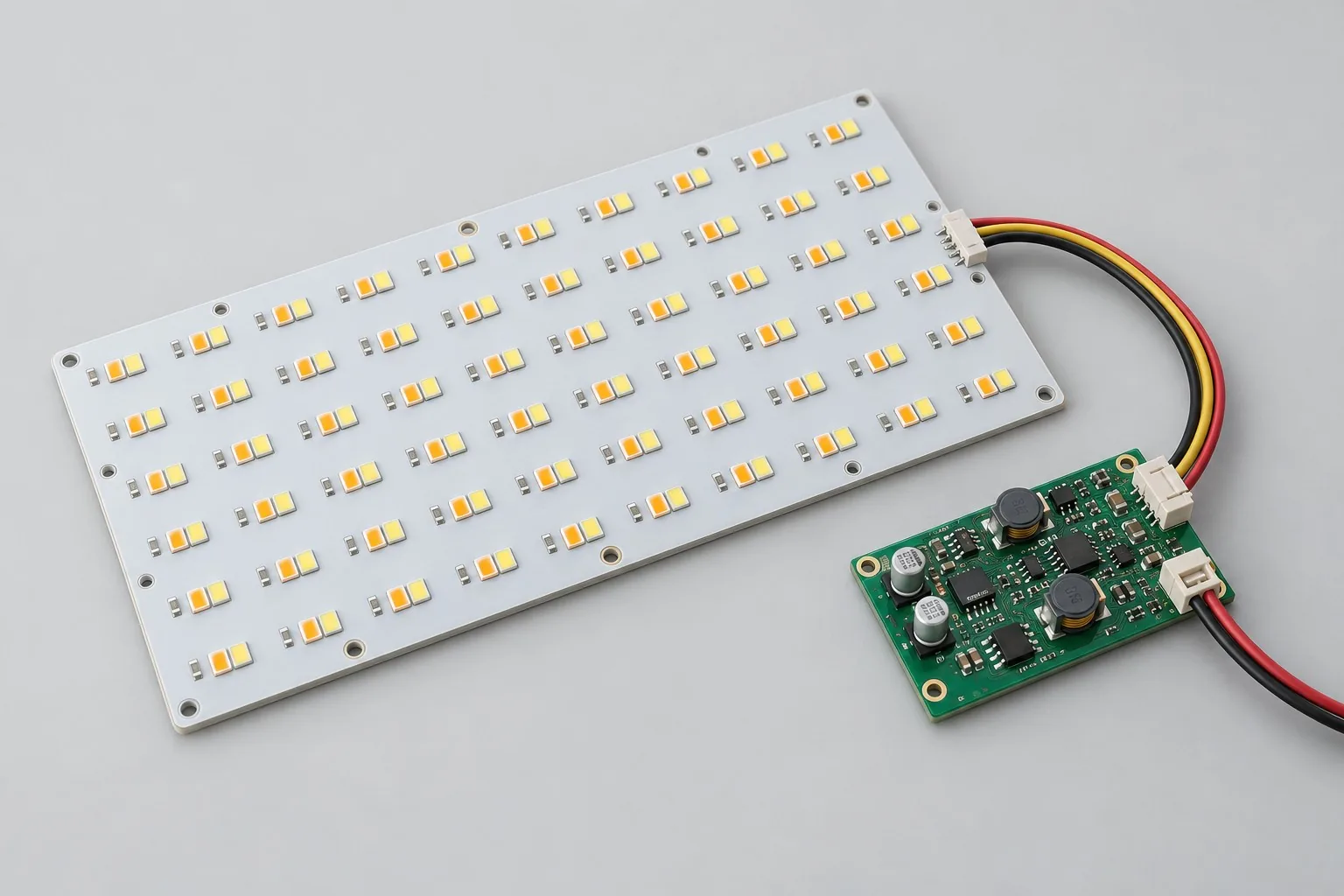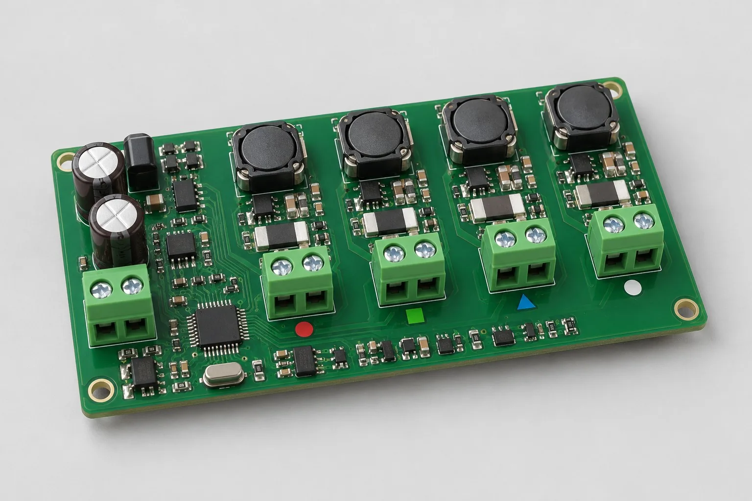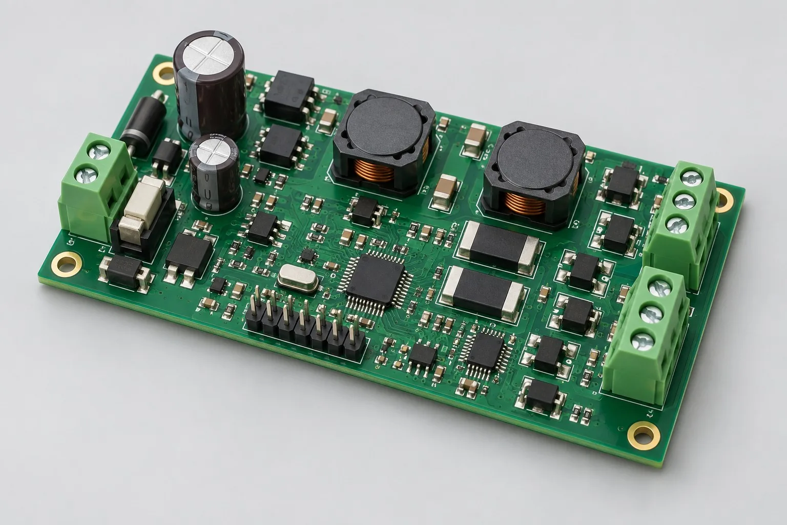
Engineering reference design · prototype validation pending
Constant-current LED design: 24V-to-LED current-regulated dimming
24V LED drivers convert DC inputs to single-string constant current with PWM/analog dimming and enable. The 350mA/700mA settings are development options. Verify string drops, ripple, low brightness, and protection for selected drivers.
Custom development reference design. The parameters below are requirement configurations and design targets; validate product performance through agreed prototype tests.
| Functional Partition | Design and verification scope |
|---|---|
| 24V input protection | Confirm 24V limits, entry protection, and total string drop, preserving buck-topology headroom. |
| Constant Current Switching Power Supply | Select LM3409-type buck controllers and MOSFETs/inductors by current, ripple, and heat. |
| LED current adjustment | Sense resistors/paths define current; settings changes require device-stress review, not resistance changes alone. |
| LED String Output | Define LED terminals/output ranges by string count, Vf, and harnesses; review opens/shorts separately. |
| Dimming Control | Configure PWM/analog dimming to actual devices. Enable, temperature readback, and MCU are agreed options. |
| Open/short / Temperature rise | Record undervoltage, open/short, and thermal derating. Separate current-regulation electrical results from brightness/flicker optics. |
How much does constant-current LED design cost, and how are quotes calculated?
Define strings/current before circuit/dimming costs. String headroom, power, protection, and thermal tests change components/verification. Low-voltage and direct mains are different projects. Quote current channels, dimming firmware, actual lights, and prototypes separately, not controller prices alone.
Quotation terms depend on the approved files, quantity, material supply, tests and delivery requirements.
Prepare a structured RFQ or use the short inquiry form.
| Quotation Items | What services are included | What to Check When Comparing Quotes |
|---|---|---|
| Circuit and PCB Design | Constant current channel, LED string voltage drop, and dimming | Reusable portions of existing designs and circuit/mechanical changes |
| Software and Validation | Ripple, Anomaly, and Thermal Test | This page covers low-voltage inputs; direct mains adds power and safety design |
| Prototype Preparation | Bare PCB, BOM procurement, assembly, and agreed prototype quantity | Whether material/component revisions, prototype quantities, and test targets match |
| Subsequent Revision | Record new requirements separately from post-test corrections | How agreed changes, source files, and validation results are delivered |
Should LED drivers use constant current or constant voltage?
Consider constant current for independent strings; strips with built-in current limiting follow their input requirements. Output architectures differ and are not interchangeable merely by 12V/24V labels.
How should 350mA and 700mA drivers be selected?
Choose current by LED limits, series/parallel structure, and cooling, then verify current/heating. Double current does not directly mean double brightness. Rebudget power/devices too.
Do LED development quotes include mains inputs?
This page covers low voltage; direct mains adds power/safety design. List strings, dimming firmware, and input range separately rather than treating mains as a minor revision.
24V-to-LED constant-current dimming reference configuration
| Configuration Field | Reference Configurations/Selections | Basis and Status |
|---|---|---|
| Finished Product Function | Single-channel LED constant current driver plus dimming | Design Objective |
| Power Supply Objective | 24V DC requirement example | Design Objective |
| Output Target | 350mA or 700mA development settings | Design Objective |
| LED Load | Series count/total drop set by LEDs and supply headroom | Design Objective |
| Component Candidate | LM3409-type buck LED controller | Design Objective |
| Dimming Interface | PWM/analog dimming selected by device capabilities | Design Objective |
| Control Interface | Optional enable, temperature readback and MCU control | Design Objective |
| Power Device | MOSFETs, inductors, and sense resistors selected by current | Design Objective |
| Layer Candidate | 2–4 layer FR-4 driver board | Design Objective |
| Thermal structure | Thermal copper + required heat sinks; separate LED board/driver possible | Design Objective |
| Protection Strategy | Undervoltage/Open-Short Response and Over-Temperature Derating | Design Objective |
| Validation outputs | Current Ripple, Dimming, Efficiency, and Temperature Rise | Design Objective |
LED String Voltage Drop and Current Step Verification
Use buck conversion when total LED voltage drop is below the input with sufficient control headroom; higher-voltage strings require boost/buck-boost selection again.
Both settings require inductor, MOSFET, and thermal checks, not sense-resistor changes alone.
Accept electrical and optical behavior separately; measure brightness/flicker with actual LEDs/mechanics.
Design budget and trade-off examples
Check design targets with engineering calculations
At reference total Vf 18V and 0.35A, LED output is 6.3W. Assuming 90% efficiency, input is approximately 7W.
Conditions and Scope of Application:Vf varies by temperature/lot; efficiency is a budget assumption. Recheck headroom, device losses, and opens/shorts.
Replace examples with selected components and record margins; calculations support design choices, while prototype records support acceptance.
24V LED constant-current dimming power and layout
- Compact switching loops; consider Kelvin sensing to avoid high-current copper errors.
- Keep PWM/analog dimming away from switching nodes; sense temperature near actual heat sources.
- Short LED-output/driver returns; assess filters/EMI for long harnesses.
LED driver board R&D input
- LED data, series/parallel structure, current, and drops
- Dimming frequency, minimum brightness, flicker, and optical requirements
- Harnesses, enclosure cooling, temperatures, and supply range
If circuit files exist, provide editable schematics, PCB, BOM, and current issues, and agree on review or revision scope. If only functions are defined, freeze this page's inputs before selection and circuit development. Agree separately on control-software and external-application responsibilities, interfaces, and acceptance.
LED driver board phase delivery
| Stage | Engineering Work for This Proposal | Reviewable Deliverables |
|---|---|---|
| Requirements and Design Freeze | Freeze strings, currents, input range, dimming, and cooling/harnesses | Functional/interface requirements, mechanical revision, acceptance conditions, and open items |
| Schematic and Component Selection | Design buck current regulation, feedback, enable/dimming, and input/output protection | Editable schematics, controlled BOM, footprint checks, and design calculations for these circuits |
| Layout and Routing | Arrange compact loops, Kelvin sensing, dimming separation, and thermal points | PCB source files, actual stackup/hole/net constraints, DRC, and assembly-dimension checks |
| Simulation/Calculation | Calculate string headroom, inductor/switch stress, ripple, efficiency, and heat | Design calculations/models, input conditions, margins, and items awaiting measurement |
| Prototype and Software | Build drivers; integrate approved current settings, dimming, and optional monitoring | Manufacturing package, LED prototypes, current/dimming configurations, wiring/protection notes; optional MCU firmware within commissioned scope |
| Testing and Version Closure | Sweep inputs/loads/dimming; verify ripple, optics, protection, and heating | Procedures, wiring, raw results, and decisions for the prototype revision; include issue/change and limitation lists |
Constant Current Dimming and Protection Verification
- Output current/ripple under input/load variation
- Low-brightness PWM/analog linearity and flicker plans
- Open-Short, Undervoltage, and Temperature Derating Response
- Continuous full-load temperature rise and efficiency measurement
Sweep inputs/loads/dimming; verify ripple, optics, protection, and heating. Reports identify equipment, conditions, revisions, and criteria, recording passed/uncovered items.
Constant current dimming and protection verification worksheet
The table turns 24V LED current-regulated dimming into checks. Freeze samples, equipment, environment, and tolerances; link results to current raw records.
| Verification Object | Pre-Production Freeze | How to Test Prototypes in Practice | Delivery and Acceptance Records |
|---|---|---|---|
| Constant Current Range | LED drop range, string count, supply, and 350/700mA development settings | Measure current/ripple with agreed input/LED-load combinations | Deliver means, ripple, and conditions; target current is not proven output for all strings |
| Dimming and Flicker | PWM/analog approach, minimum brightness, and flicker criteria | Sweep agreed dimming settings; measure current/optical response | Retain duty, frequency, light output, low-brightness nonlinearity, and equipment |
| Thermal and Protection | Cooling, maximum ambient, derating/open/short states | Reach agreed full-load thermal stability; apply approved faults | Deliver temperatures, efficiency, and protection/recovery; link criteria to device revisions |
Manufacturing and assembly coordination for this design
- Review thermal-pad solder volume, inductor fastening, and high-current terminals together.
- Use controlled LED loads/actual strings; avoid extra measurement wiring drops.
Link design revisions to schematics, BOM, PCB, fabrication, and software documentation. When fabricators adjust stackup, materials, or holes, or Assembly parties propose substitutions, recheck critical electrical and test conditions together.
Common questions on purchasing and customization
How much does constant-current LED design cost, and how are quotes calculated?
A project-specific quotation requires review of the available files, quantity, materials, requested tests, delivery destination, taxes, shipping, and trade terms. Complete development separately prices circuits, firmware, prototypes, and verification. Any formula on this page organizes cost inputs; it is not a quoted rate.View cost items, calculation conditions, and sources.
How should LED opens/shorts enter tests?
Separately check faults, current, heat, and recovery under approved conditions. Uncontrolled shorts do not replace protection design.
What should delivered LED dimming firmware explain?
Define interfaces, settings, frequency, and minimum-brightness behavior. Retain light-group conditions and tables for prototype/later revision reproduction.
How should driver budgets select baseline and dimming packages?
Freeze 24V, string drops, and 350mA/700mA settings. Baseline work covers current regulation/faults. Separate PWM/analog dimming, MCU temperature readback, and low-brightness verification. Identify existing lights/heat sinks by revision; channel count does not price complete luminaires.
Which devices must be confirmed before LED layout-only work?
Confirm LM3409-type applicability, MOSFETs, inductors, sense resistors, strings, and cooling, with loop/sensing constraints. Without calculations/selection, design circuits first. Completed routing does not establish ripple or actual string current compliance.
Does existing PWM control still need dimming development?
Check frequency, duty range, enable timing, and low brightness against selected drivers. Fixed customer PWM may omit higher-level scenes, but ripple/startup/recovery still need integration. Temperature derating adds sensing/control mappings.
What source code and calculations should constant-current designs deliver?
Retain inductor/resistor selection, string headroom/loops, current settings, and interfaces. Commissioned firmware includes dimming/derating. Reports identify lights, input ranges, ripple, and thermal conditions, supporting headroom review after LED changes rather than resistor changes alone.
What is reusable versus new when changing 350mA to 700mA?
Controllers may remain, but check power devices, inductor saturation, resistors, supplies, and cooling, revalidating faults/ripple. Separate calculations, hardware, and thermal/dimming regression. Double current is not a free parameter edit.
Can low-voltage drivers directly become mains LED drivers?
Inputs cannot be reused directly. Mains adds rectification, conversion, isolation/insulation coordination, and complete tests. Some downstream dimming requirements may remain, but define input/safety work separately. The 24V reference excludes direct mains.
How should RFQ files be prepared for constant-current LED design?
Initially describe functions, uses, and files. Quotes confirm LED data/string structure/current/drops; dimming frequency/minimum/flicker/optics; harnesses/cooling/temperatures/supplies. Provide editable schematics/PCB/BOM or fault-prototype revisions/reproduction records. List missing-data review tasks to avoid differing assumptions.
How should constant-current LED prototype verification costs be compared by condition?
Fix quantities, revisions, equipment, and criteria. Separately check current: fixed LED drops/string counts/supply/350/700mA settings, agreed-load current/ripple; dimming/flicker: fixed approaches/minimums/criteria, swept settings/current/optics; thermal/protection: fixed cooling/ambient/derating/open/short states, full-load stability and approved faults. Specify raw-data/issue-closure delivery. One power-on pass is not full verification.
Compare related designs and plan the next step
Tunable-white LED board and color-mixing control design · RGBW four-channel constant-current color-mixing control board design
Return LED PCB Design Selection · Select solution by device function · Discuss your design requirements
Documentation Basis and Boundaries
Engineering reference | LM3409 selection conditions and board verification: LM3409 references buck current regulation/dimming; complete-board current, efficiency, and optics require actual strings/thermal conditions.