
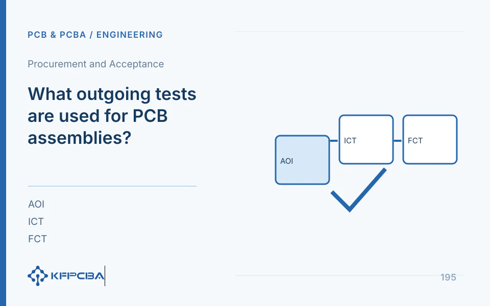
PCB assembly outgoing inspection: define coverage and results first
PCB assembly outgoing inspection should match product risks and order acceptance requirements. Visual inspection, AOI, hidden-joint inspection, electrical testing, functional testing, aging, and reliability testing cannot replace one another, and not every board requires every test in every batch.
Inspection coverage versus blind spot comparison
| project | Primary Use | Blind Spots or Prerequisites | Order Agreements Required |
|---|---|---|---|
| Appearance/Visual Inspection | Components, polarity, contamination, and visible solder joints | Unable to confirm all bottom solder joints and functionality | Critical items, sampling/full inspection, and acceptance basis |
| AOI | Visual Inspection of Placed Components and Solder Joints | Program and visibility impact coverage | Actual equipment, programs, false-call review, and records |
| Hidden solder joint visibility | BGA/QFN solder-joint geometry and some defects | Cannot Independently Verify All Electrical Functions | In-house/outsourced equipment, methods, scope, and acceptance |
| ICT or Node Testing | Network Accessibility and Device Electrical Relationships | Requires test points, fixtures, and programs; coverage is not automatically 100% | Test points, parameters, fixtures, and failure criteria |
| FCT | Specified power, loads, interfaces, and firmware operating conditions | Functions and operating states not exercised by the test remain unverified | Cases, limits, revisions, cycle time, and reports |
| Aging | Operating changes under agreed time/load/temperature conditions | Cannot Directly Convert Arbitrary Service Life | Conditions, monitoring, anomaly handling, and quantity limits |
| Reliability Testing | Sample behavior under agreed environment or stress | Conclusions are limited by the sample configuration and test scope | Design basis, samples, execution responsibilities, and reports |
How to form an executable acceptance table
For each item, specify the test target, method, stimulus, and acceptance limits, including sampling, responsible operator, equipment/software, and result fields. IPC's official descriptions distinguish soldering-process requirements from post-assembly acceptance; confirm applicable revisions, classes, and customer-specific requirements in the order. This page does not reproduce complete acceptance tables from paid standards.
Example: defining control-board test coverage
If an order includes programming and dual outputs, first link the firmware checksum, then validate each output's load, protection, and recovery separately; passing visual inspection does not establish correct outputs. If fixtures stimulate only some channels, report actual coverage and assign responsibility for remaining tests. Also check changes to wire order and interface access before and after enclosure installation.
Record Keeping and Exception Closure
Link PCB/BOM/firmware/test-program revisions, batch or SN, inspection results, and approval records; customer requirements determine whether SNs are needed and the retention period. Record rework causes and retests separately, without combining first-pass results with post-rework passes. Distinguish reliability validation from outgoing inspection for each batch; do not transfer PCB HALT/CAF and service-life claims directly to PCB assemblies.
The customer provides product class and acceptance requirements, critical functions, sampling, and reporting requirements. Engineering returns a coverage matrix, blind spots, fixture/software responsibilities, execution location, acceptance, and post-rework retesting. This article lists method choices and does not establish that KFPCBA has all AOI, radiographic, or ICT equipment.
Resolve the open decisions before placing the order
Product testing services: Implement Fixtures, Conditions, and Reports.
Quality and Acceptance: Define Approval, Sampling, and Traceability.
SMT Defect Troubleshooting: Verify defects based on evidence. · Procurement and Acceptance Knowledge
Engineering reference | IPC soldering processes and assembly acceptance: agreeing on inspection criteria. A basis for methods and selection; not evidence of KFPCBA capabilities
Engineering reference | BGA assembly methods: pad definitions, warpage, and hidden solder joints. A basis for methods and selection; not evidence of KFPCBA capabilities
Build a test coverage matrix from the functional list
The following matrix is the author's organizational method. List the work the product must perform first, then explain how each inspection detects corresponding risks. Equipment capability does not mean the current program performs that check; some risks require two types of supporting evidence. IPC's public introductions distinguish process requirements from finished-product acceptability, while TI's package guide explains inspection of bottom connections. Neither replaces the current product's functional specification.
| Object | Stimulus and Conditions | Observe Output | Recording Boundary |
|---|---|---|---|
| Multi-channel Output | Specify load and switch status per channel | Voltage/Current, Actuation, and Protection Recovery | Result per channel, mark uninstalled option separately |
| Communication Interface | Specify Remote End, Protocol, and Error Scenarios | Message, throughput, or recovery behavior | All actual ports and program version |
| Acquisition Channel | Controlled input and calibration conditions | Readings, Error, and Status | Channels and measurement range, limit sources |
| Firmware and Device Identity | Controlled firmware image and device-identity assignment rules | Validation, version, and uniqueness | Board number and write log association |
Limits come from approved product specifications, component requirements, and applicable requirements; test engineering translates them into executable programs. Items without limits or methods may initially be marked undefined. Do not insert a common industry value and claim everything passed. Feed test-point and fixture-accessibility concerns back to design early, rather than discovering inaccessible critical nodes at the last moment in volume production.
Explain the denominator first for coverage ratio
Engineering calculation example: on an 8-channel acquisition board, the fixture stimulates only 6 channels, giving channel-count coverage of 6÷8=75%. This does not mean 75% whole-board functional coverage, because measurement ranges, states, and protection may have different cases; the remaining 2 channels cannot be marked passed. List actual channels and states, then assign supplemental-test responsibilities. Passing one input point on a channel does not establish compliance across its entire measurement range.
What does a reproducible test result require?
| Field Group | Suggested Content |
|---|---|
| Identity | Board ID or batch, PCB and BOM revisions, and actual options |
| Execution | Time, program, fixture, supporting equipment, and calibration status |
| Condition | Power, loads, environment, inputs, and interface combinations |
| Result | Actual values or states, limit revision, and failure codes |
| Disposition | Rework, material replacement, retest, approval, and delivery status |
Retaining raw values generally helps investigate drift more than retaining only PASS, but contracts and actual systems determine content and retention periods. Define manual recording methods for items without test output. Fixture changes, probe wear, and program revisions can also affect results, requiring verification and change records; repeated tests until a contact problem yields a pass must not be treated as having no anomaly.
Preserve the failed configuration before retesting
Method example: if one channel's load protection fails on a dual-channel driver board, first retain failure conditions and logs, then distinguish fixture, program, supporting power equipment, and board causes. Record changes when swapping loads for diagnosis; do not remove cases to make the board pass. After rework, run the original failed case and retest the other channel, power, and recovery states according to impact; retain the initial failure and final result.
If harnesses or enclosures are installed after final testing, assess whether wiring, access, and thermal states need retesting. Report aging and reliability sample results separately, identifying conditions and samples; do not extend them to every function on every board or arbitrary service life. Delivery reports should let customers distinguish tested, untested, not applicable, and pending items, rather than automatically interpreting blanks as passes.
Source material and applicable scope
- IPC, IPC Releases J Revisions to Two Leading Standards for Electronics Assembly; public news version 2024-04-08; checked 2026-10-17; sections: standards responsibilities and revision introduction. Supports the distinction between process requirements and assembly acceptability; not the complete formal standards.
- Texas Instruments, “QFN and SON PCB Attachment”; revision SLUA271C, 2023-12; checked 2026-10-17; sections 3 PCB Design, 4 Screen Printing, 5 Assembly, 6 Rework; supports QFN/SON process methods and conditional starting points, not universal acceptance limits.
How should I choose AOI, X-ray, ICT, and FCT and compare testing costs?
AOI primarily examines visible assembly features; X-ray examines some hidden structures; ICT electrically tests accessible nodes; FCT validates specified functions and states. They cover different defects, so choosing the cheapest by equipment name cannot establish that the entire board is acceptable.
Compare costs and verification under the same conditions
For BGAs, list hidden-joint risks first; for acquisition boards, channels and calibration; for driver boards, loads and protection. Separate fixture development, per-board testing, and retesting in quotations, and require test records linked to board IDs, programs, and limit revisions.
View services and configurations related to this question or Request a project quotation. For initial discussions, describe the intended use, available documentation, and expected quantity.
Related procurement and acceptance Q&A
How should I choose AOI, X-ray, ICT, and FCT and compare testing costs?
Read: How should I choose AOI, X-ray, ICT, and FCT and compare testing costs?
How should fixture-development costs and per-board FCT costs be compared separately?
Preparation includes fixtures, software, and cases; per-board execution includes specified power, loads, interfaces, and state records. Align coverage and limits first, then compare preparation, execution, and post-rework retesting.
Read: How should I choose AOI, X-ray, ICT, and FCT and compare testing costs?
Can a whole board be marked functionally passed if only some channels are tested?
Records should identify channels and cases actually stimulated; assign responsibility for testing uncovered portions. Passing visual inspection or one channel cannot be extended to all functions on the board.
Can aging and reliability testing replace each other?
They answer different questions under agreed conditions; operating changes during aging cannot directly establish life, and reliability sample results do not automatically become batch-release records.
View: Test Coverage vs. Blind Spot Comparison
Can a post-rework pass count as an initial inspection pass?
Retain initial inspection anomalies, rework causes, and retests, linked to board IDs and PCB/BOM/firmware/test revisions. Record first-pass results separately from post-rework passes to support investigation of batch differences.
Write one test requirement as a release record
“100% tested” has no useful meaning without naming the feature, method, limit and denominator. For example, if an assembled controller has two independently switched outputs, a functional test that toggles only output A cannot prove output B. A release row should identify both outputs, the applied input or load, the measured result, pass/fail limit, test revision, board identifier and operator or equipment record. State whether every shipped unit receives that step or whether it is a sample check.
AOI may inspect visible placement and solder features; it does not exercise product behavior. X-ray can reveal selected hidden structures but cannot establish that firmware and power sequencing work. ICT depends on accessible nodes and a defined fixture or program. FCT verifies only the functions and operating conditions actually exercised. Select a combination from the product's failure risks, then list any remaining blind spot in the acceptance agreement.
RFQ handoff: name the test evidence
Send the function list, sample or 100% coverage requirement, limits, fixture ownership and required records with the test scope. The project inquiry can identify an unresolved method.
