
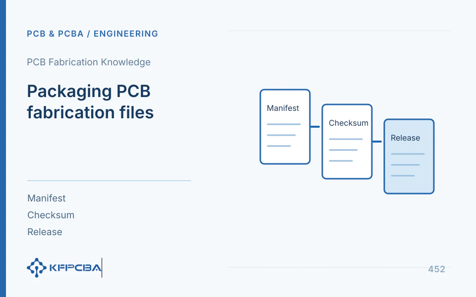
A reliable PCB fabrication package contains consistent, parseable, traceable files. Graphics, drilling, layer order, and notes express one revision; receivers must not assemble it from emails/chats. After changes, issue a complete new package and supersession link, not a context-free patch attachment.
Define data scope based on manufacturing objects first
Ucamco's “PCB Fabrication Data — Design to Fabrication Data Transfer,” V6, September 2015, covers coordinates, outlines, layer structures, drilling, netlists, and nongraphical data. It is a transfer guide, not a complete specification for all current software formats. Its coordination of data with explanations remains useful for review.
| Document Group | Required Content | Inspection Target |
|---|---|---|
| Graphics and Vias | Current layers, outline, holes, and slots | Units, origin, direction, and layer pair consistency |
| Manufacturing Structure | Materials, stackup, copper weight, hole treatment, and surfaces | Explicit requirements that graphics cannot establish automatically |
| Connection Verification | Netlist and agreement check inputs for the same version | Use the netlist to cross-check the connectivity represented by the artwork. |
| Version Description | Lists, revision summaries, approvals, and checksums | Uniquely determine current production basis |
If assembly is included, group BOM, pick-and-place files, DNP, drawings, and test inputs separately while referencing the same product revision. Fabrication Gerber alone cannot define assembly procurement scope.
An example of a reusable directory configuration
Engineering example: product P, revision R4, package P_R4_fab. Organize fabrication, assembly, and release folders: fabrication contains graphics, drilling, drawings, and stackup; assembly contains inputs only if ordered; release contains lists/change notes. These folder names are not mandatory; each file needs a clear role.
- List filenames, functions, revisions, and required status; exclude backups from production files.
- Use the same structure identifier for stackup/drawings and match hole tables to current drill files.
- Describe changes from R3 to R4 and identify superseded packages.
- After freezing, calculate and archive checksums, then distribute to named recipients.
- Receivers confirm identity, completeness, and clarifications; fabrication begins after closure.
Retain timestamps if useful, but not as unique revision identity. Compression/transfer can change them; checksums and controlled identifiers better establish the same package.
Units and coordinates undergo one reproducible check
Select a known spacing/dimension, such as 25.4 mm hole spacing equal to 1 in. Imported values of 1 mm or 645.16 mm suggest a 25.4 unit factor. Check unit declarations/coordinate formats instead of scaling by appearance. Keep outlines, drilling, and all layers on common coordinates; manually aligning one layer in a viewer is insufficient.
Check mirroring using asymmetric locating holes, notches, or text. If outlines show both individual boards and panel diagrams, identify machining data versus explanation. Keep dimension/annotation lines out of outline paths to prevent unintended routing.
Manufacturing notes supplement requirements that graphics cannot express
Give explicit objects for layer copper weight, materials/dielectric thickness, finish, hole treatment, impedance, and mechanical tolerances. Identify drill versus finished diameter, base versus finished copper, and special-region boundaries. State standard revisions and product requirements instead of “per IPC,” leaving class/items to guesswork.
| Ambiguous Notation | Additional inputs required | Corresponding Output |
|---|---|---|
| Gold Plating | Treatment system, regions, and applicable inspection requirements | Controlled surface requirements |
| Via | Via group, fill, cover, and flatness targets | Via Treatment Table |
| Impedance Control | Network groups, layers, targets, and criteria | Calculations, test coupons, and records |
| High-Frequency Materials | Full part number, dielectric thickness, copper foil, and alternatives | Layer-by-layer stackup approval |
Drawings explain production requirements; screenshots cannot replace precise data. Resolve graphic/text conflicts with approved conclusions, then update every representation.
How to convert patch attachments into a complete revision
If R3 was sent and one drill file changes, do not let the factory retain the rest of R3 and swap that file. Update sources and reexport complete R4, checking effects on hole tables, netlists, drawings, and Job. Unchanged files can retain contents, but references within the current package must align.
Engineering clarifications are controlled changes too. Record issue, owner, conclusion, affected files, and closure revision. Assess electrical/assembly impacts before approving proposed fabrication adjustments. A verbal “yes” without files/structure leaves later teams unable to establish what was made.
Do not confuse incoming acceptance with production acceptance
Receiving checks establish file completeness/consistency; engineering review confirms the specific manufacturing combination; finished inspection establishes agreed delivered-board results. These are separate stages. Receiving an archive, opening files, or issuing a quotation does not replace later statuses.
Receiving records should identify at least package number, file count/functions, tools/versions, and closed/open issues. Link board identification to package number in production. For repeat orders, name the approved package instead of relying solely on an old chat attachment called “final.”
How to quickly locate common data errors
For global copper/drill offsets, check origins/export scope; wrong layer count, obsolete remnants/lists; thickness conflicts, stackup/drawings; wrong slots, milling data/annotations; short risks, netlist cross-checks/plane polarity. Revise source data and recheck each, rather than hiding errors in the viewer.
Identical checksums can coexist with engineering errors: they verify transfer identity, not design intent. Retain separate evidence for file lists, independent viewing, and engineering checks to reduce repeated questions without false release.
How clarification records follow the final package
Give each clarification an identifier, description, affected files, owner, and conclusion. Link explanations of existing definitions; changes to holes, materials, or geometry require controlled-source updates/reissue. Distinguish explanation from physical change so one response does not become permanent substitution permission.
Final lists identify clarifications incorporated into files, instructions receivers must still execute, and applicable lots. Recheck old clarifications at new releases; prior tolerance concessions do not automatically apply to new orders. Equal product names do not establish unchanged requirements.
For multiple receivers, distribute the same package identity and retain individual acknowledgments. If one finds an error, update everyone rather than patching only that party. Document control need not choose engineering parameters but must give every executor the same approved revision.
Archive source revisions, released packages, change summaries, checksums, and inspection records where needed. Historical packages explain past decisions; current packages execute production. Clear identities allow reconstruction of past conditions instead of only finding today's changed files.
Frequently Asked Questions
Does encrypted zip file mean data is controlled
Encryption controls access; revision control still needs lists, approval, and traceability. Their purposes differ.
Does a single change require a new version?
Changes affecting production require explicit new identity and supersession. See Gerber layer functions, manufacturing combinations and the delivery checklist.
Source material and applicable scope
- Ucamco; Karel Tavernier, “PCB Fabrication Data — Design to Fabrication Data Transfer”; V6, September 2015; checked on 2026-10-17; relevant chapters: 5, 6, 8, 9, 11, 13, 15, 16, 20. Supports coordinates, layer order, holes, netlists, and package responsibilities. Directories/revision workflows are engineering guidance; the old guide is not treated as a complete current format specification.
Use a package manifest before transferring the archive
Include a manifest that names the board revision, native design reference, export date, units, copper layer order and each file's intended function. List drill files separately by plated and non-plated purpose if that distinction exists. State whether the Gerber data contains X2 attributes or whether the recipient must rely on an approved layer map and drawing. Ucamco's Gerber documentation defines file-function metadata; an ambiguous filename alone does not establish layer position.
| Receiver check | Hold condition |
|---|---|
| Import all layers at one origin and scale | Outline, drill or copper fails to align |
| Confirm stackup and layer roles | One layer has no agreed function or order |
| Compare notes, drawing and export revision | Material, thickness, finish or revision conflicts |
After a correction, send a complete superseding archive with a new identity and a short change log. Do not ask the fabricator to assemble a final release from scattered email attachments.
Fabrication handoff: send one complete archive
Package the manifest, graphics, drill data, layer map, stackup and engineering notes under one revision. Review the PCB fabrication scope or send a project inquiry if a file is still missing.
